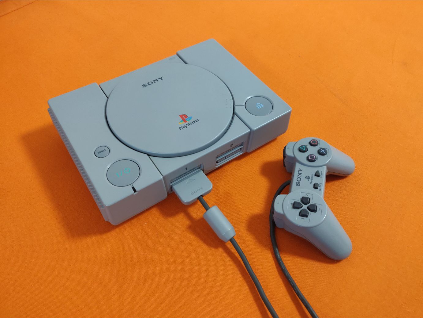
My brother has always been a fan of the first Playstation. We’ve never had one in our family but we both grew up playing on our friends consoles. And even today both of us still love the low-fi style of the early 3D games released at that time.
For the past year I’ve had an idea of giving him a Playstation 1 as a birthday gift but I wanted to take it a step further, make it a bit more modern internally; by converting it to a Raspberry Pi computer with a Playstation emulator.
Prepare for a long post with a lot of images!
The case
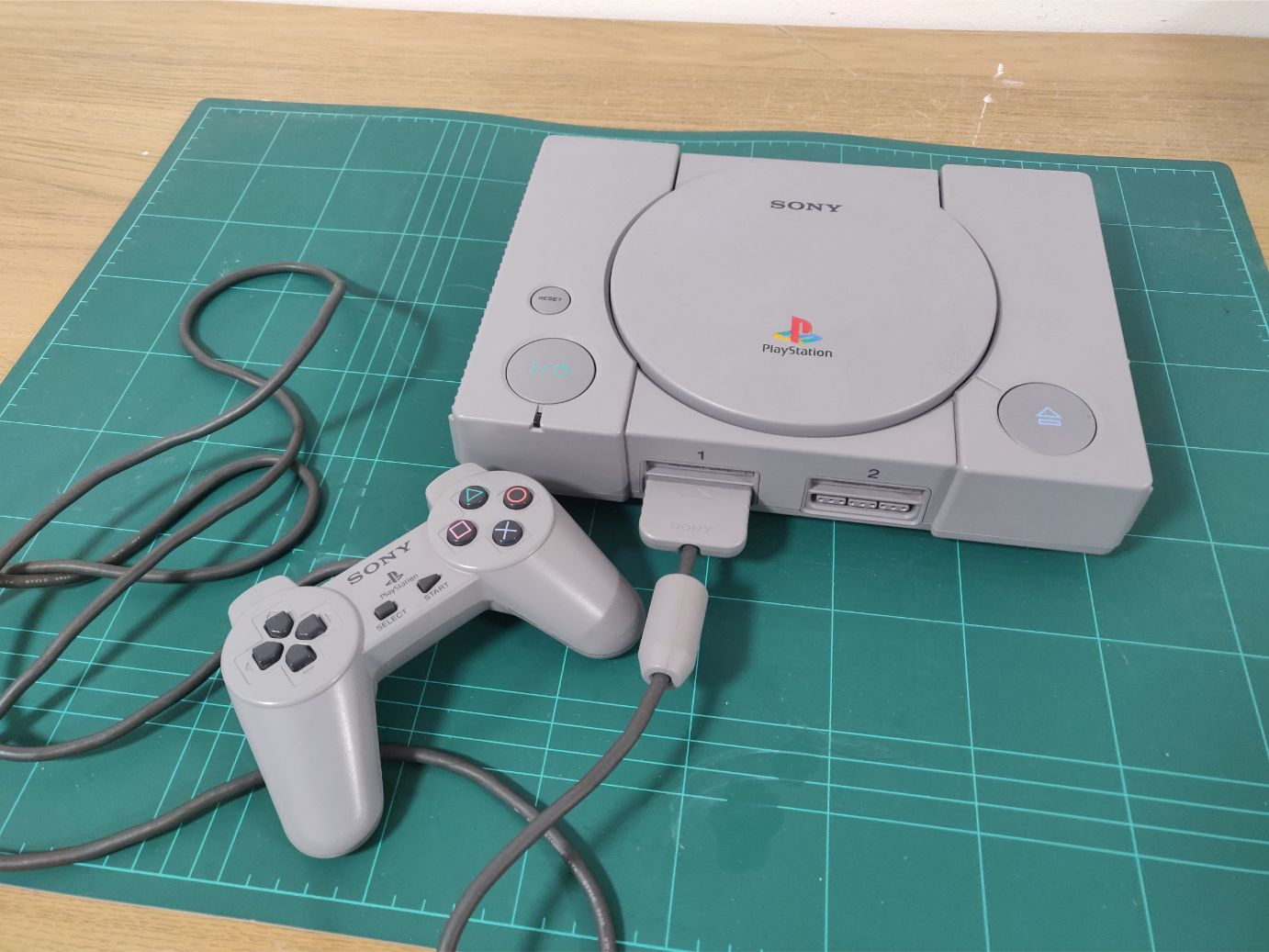
Initially I planned on 3D printing a case but I scrapped that idea as I felt it would take too much time and never live up to the original anyway. So instead I found one used in good shape for 20 euro. I believe this is model SCPH-5552.
My absolute main goal during this project was to keep it as close visually as possible to an unmodified case. I designed all parts in this project with this goal in mind.
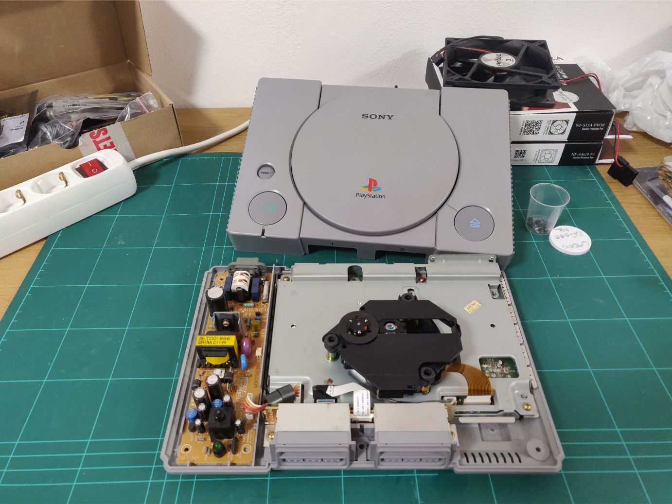
As this was a functional PS1 I had to first gut all the hardware from its inside. It felt a bit sad to discard the functional hardware but luckily I might have someone who wants to make something out of it.
In the image above you can see the power supply and disc drive, with the motherboard hiding out underneath. I was a bit surprised how much unused space the case has.
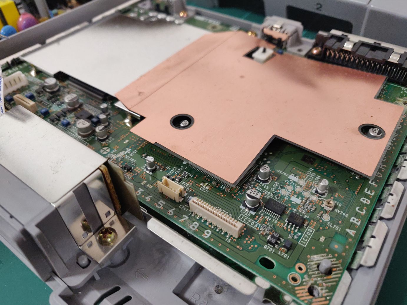
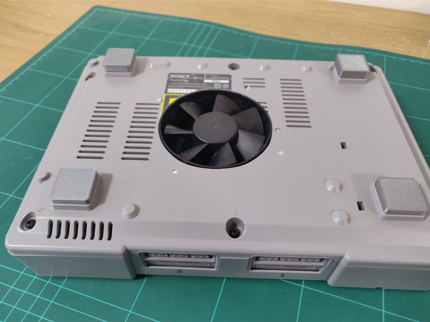
Removing the drive and metal plate you can see the motherboard. Note that there is no active cooling in the case! It’s completely passively cooled.
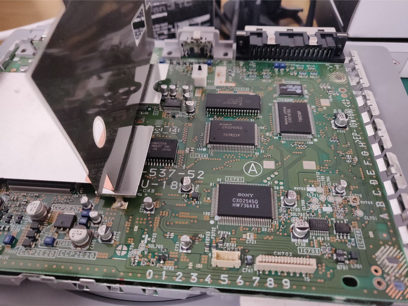
It seems that the copper-colored plastic shields the circuits from the plate above.
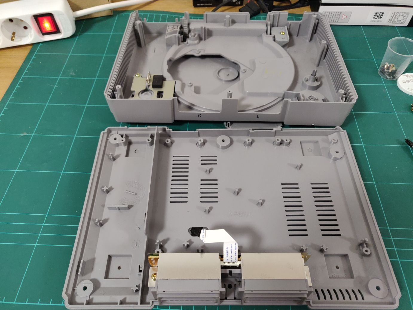
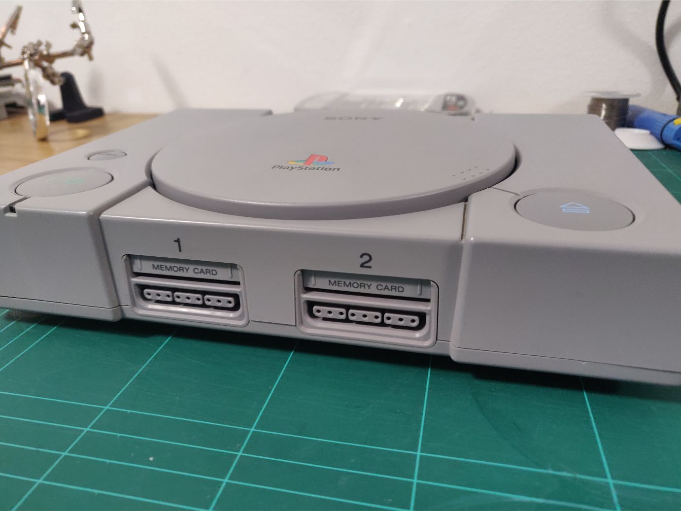
Here the case has been stripped of all parts I won’t have any use for. I will use the controller ports and memory slots in the front though.
I would like to note how incredibly easy it was to take things apart in this case, everything was modular and separated easily.
Controllers & USB
Following my goal of keeping things as similar as possible to the original I had planned on making the controller ports work with the PS1 controllers.
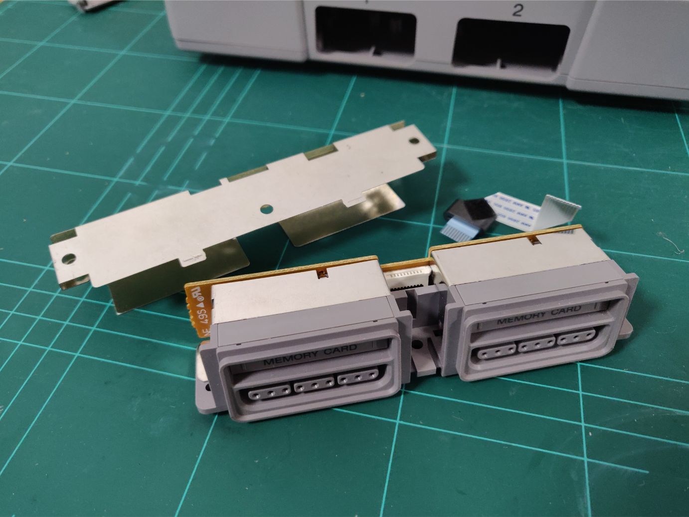
The memory card slots I wanted to convert to USB ports, which would be hiding behind the labeled hatches.

This thing above was my ticket to getting the controllers working. I found this PS1 to USB adapter for cheap online and some quick testing showed that it worked perfectly. I had already removed the casing here but further work was to be done on it.
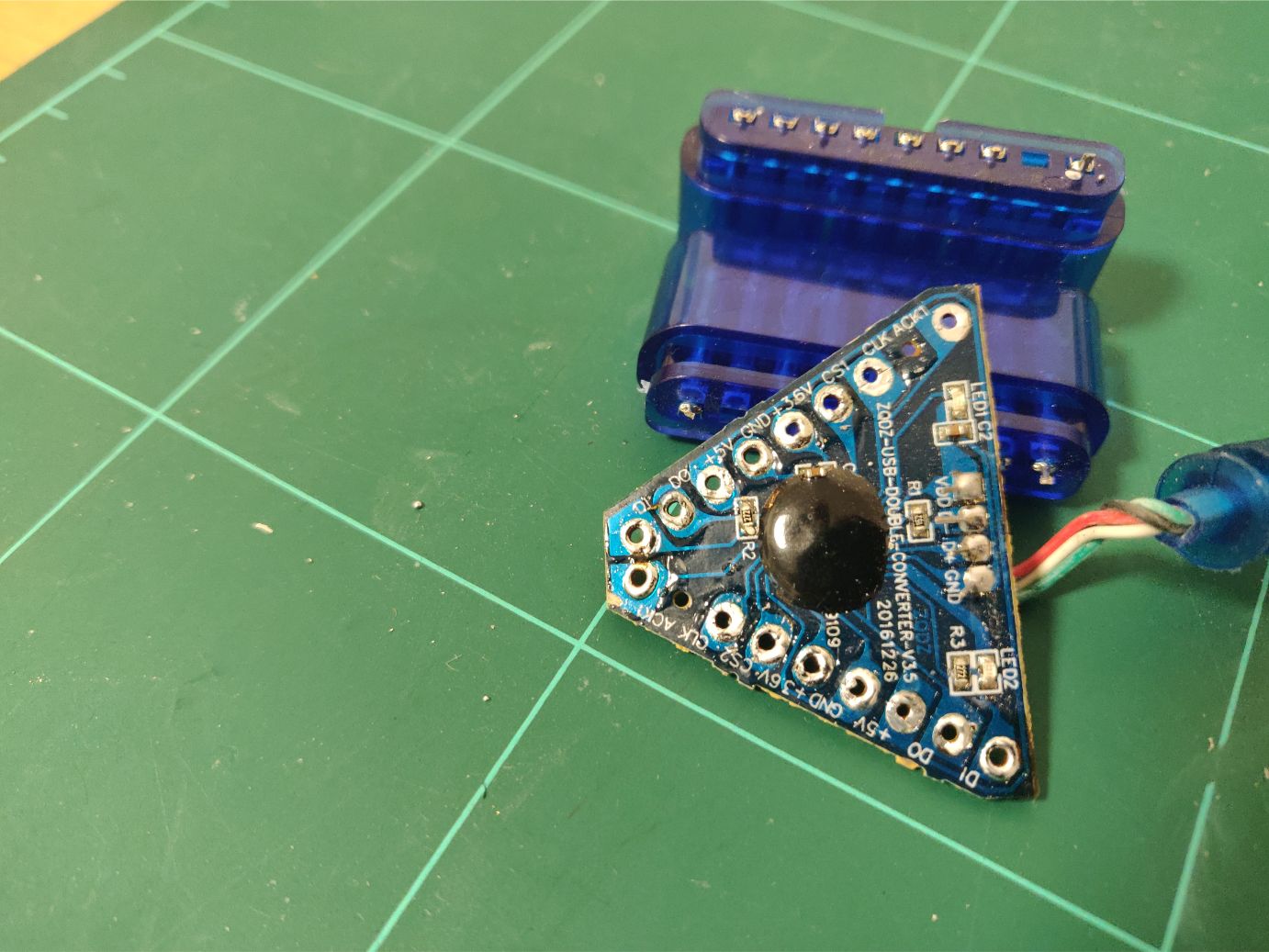
Like removing the current connectors to get them soldered to the PS1 ports. First desoldering.
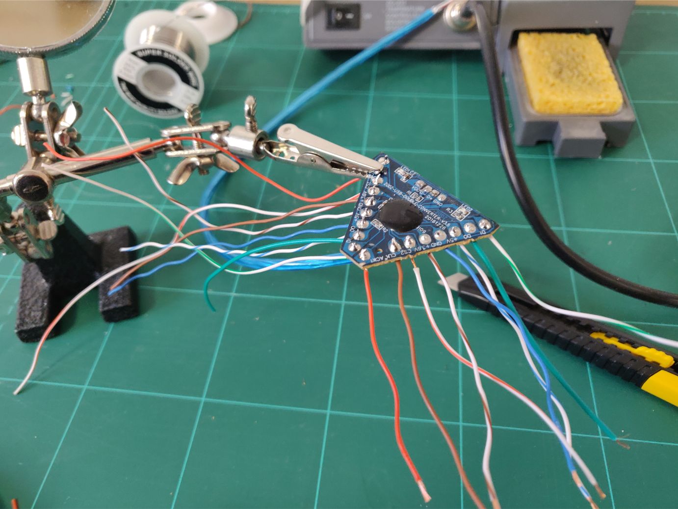
Then resoldering new cables. It almost looks like a spider.
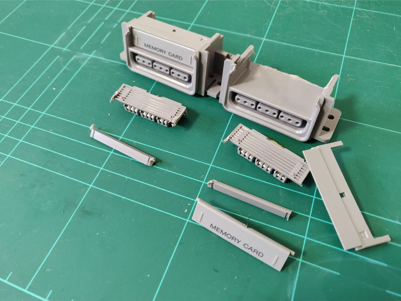
As I mentioned I wanted to have a USB port behind each memory card slot. Turns out that a lot of USB connectors wouldn’t fit in the card slot.
I was unsure how to proceed but decided I would heighten the slot by removing the top and then 3D printing a new one.
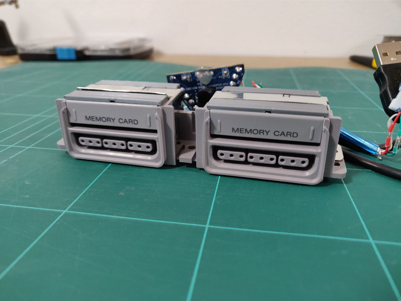
And it worked! I sadly don’t have any more in progress photos here but safe to say, it took me quite a while to design and make sure everything fit nicely.
I had to elevate the hatches to make them align with the top of the now taller slot, leaving a gap at the bottom. But I actually think it works, the darkness in the gap is similar to the darkness around the controller ports.
I wanted to reuse the metal plate that held down the piece from before but my new print made it a bit too tall. I compromised by bending the front part a bit which worked well, everything sits very snuggly.
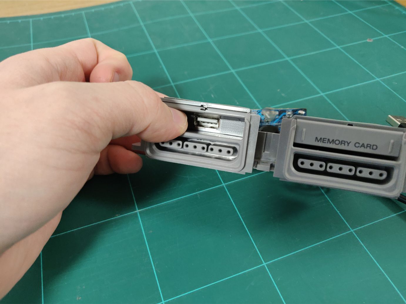
Revealing the USB port. There is a slight funneling going towards the USB port, it helps you align your cable to the port (as you push the connector in blindly through the hatch).
It’s noticeable but I think it fits in well enough.
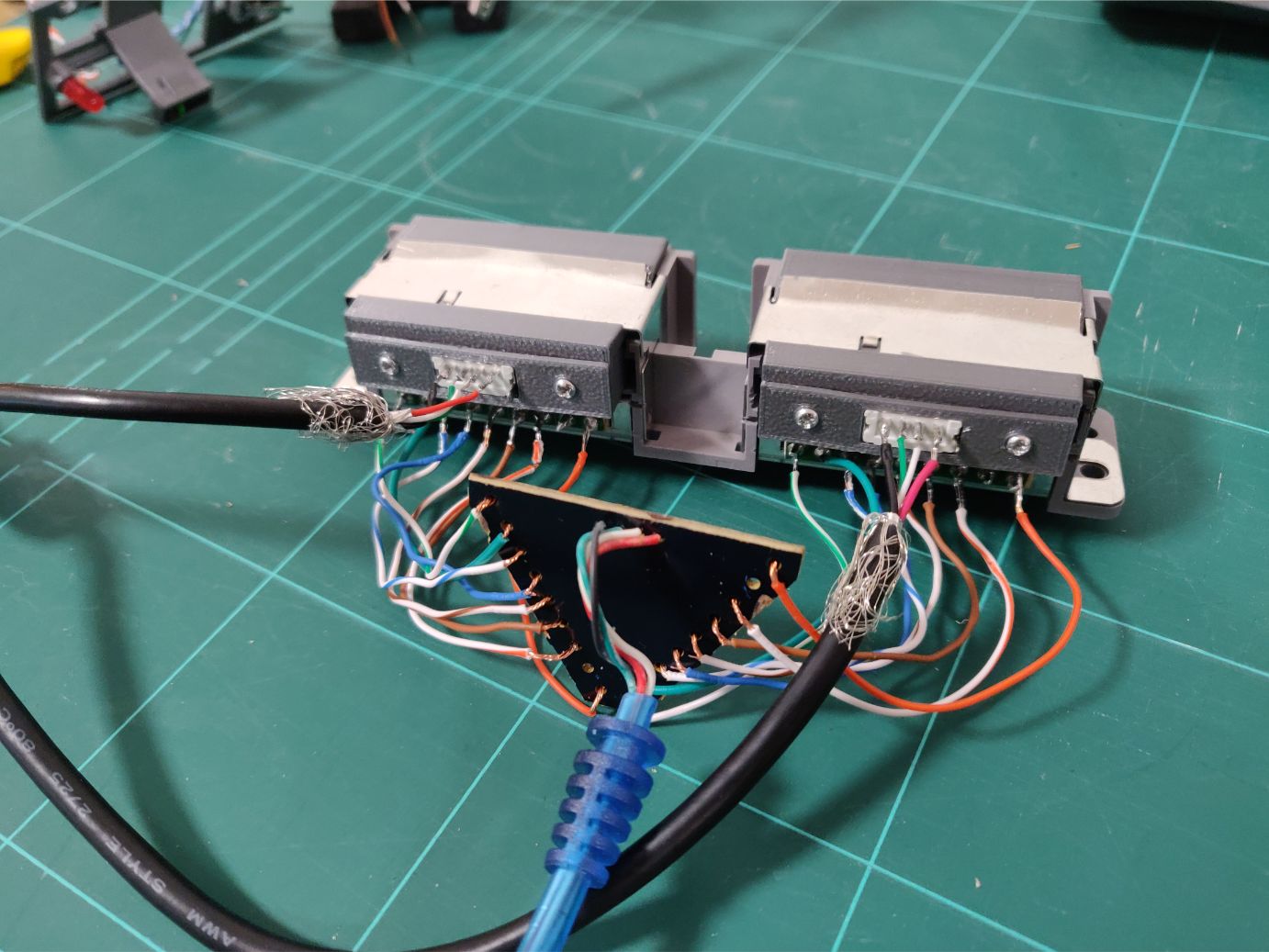
And this is what the soldering looks like. I soldered the controller cables to the pre-existing PCB solderpoints.
Console buttons
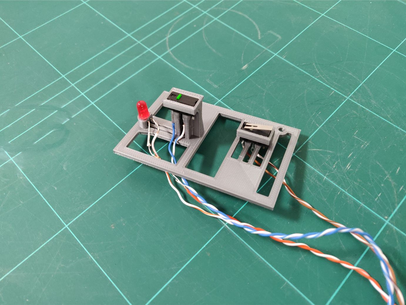
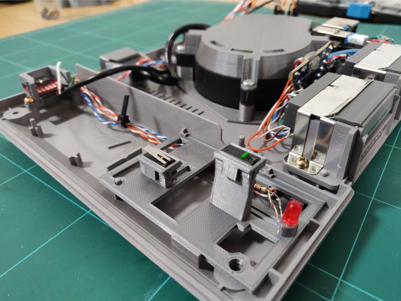
Once again in keeping with the original functionality I had to get the power & reset buttons working, together with the power LED. This is the piece that holds those switches and the LED.
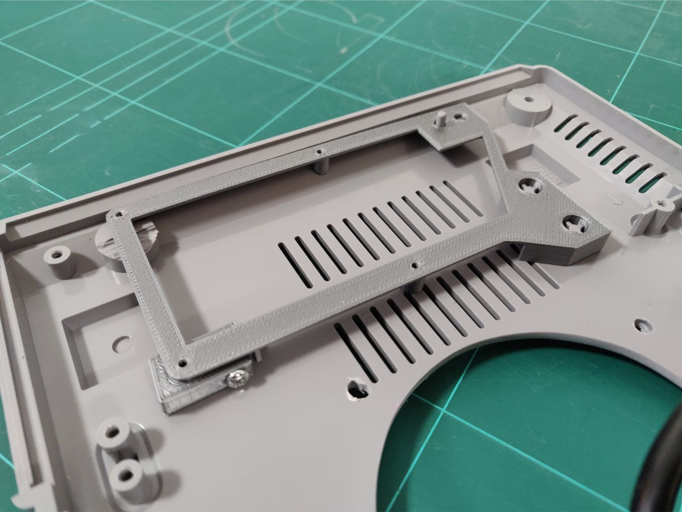
I really wanted to make the top part of the case to be completely unconnected to the hardware, similarly to how it works in the original. I didn’t want to have to disconnect any cables just to remove the top.
So with a lot of measuring I created this plate that fits into existing screw holes. They’re aligned perfectly to the buttons in the top above.
Oh, and the reset-button is a bit different as it doesn’t restart the game, instead it exits the current emulator game and returns to the emulator list.
The machine
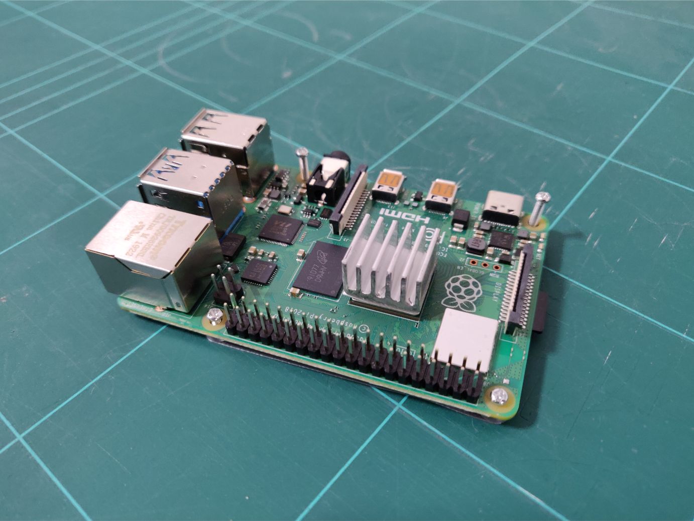
This is the machine that powers it all. I won this Raspberry Pi 4 (RPi 4) in a contest this summer and I felt that this was the perfect project to use it in. The CPU heatsink I cut from a larger heatsink I had found in an old PSU from before.
For the RPi-mount I took inspiration from a similar project, the great Playstation with Raspberry Pi 3 project. The way he/she solved fixing the mount to the case is brilliant, with a sacrificed layer jammed with two case extrusions and clamping to another case extrusion using a screw.
So I borrowed those ideas but moved my mount closer to the right edge of the case.
Need input
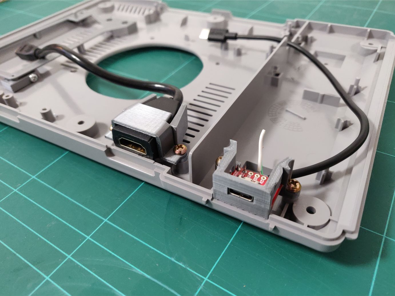
I didn’t want to clutter the back with a bunch of different connections. An HDMI-port for video and USB-C for charging was enough, wifi will do for network connectivity.
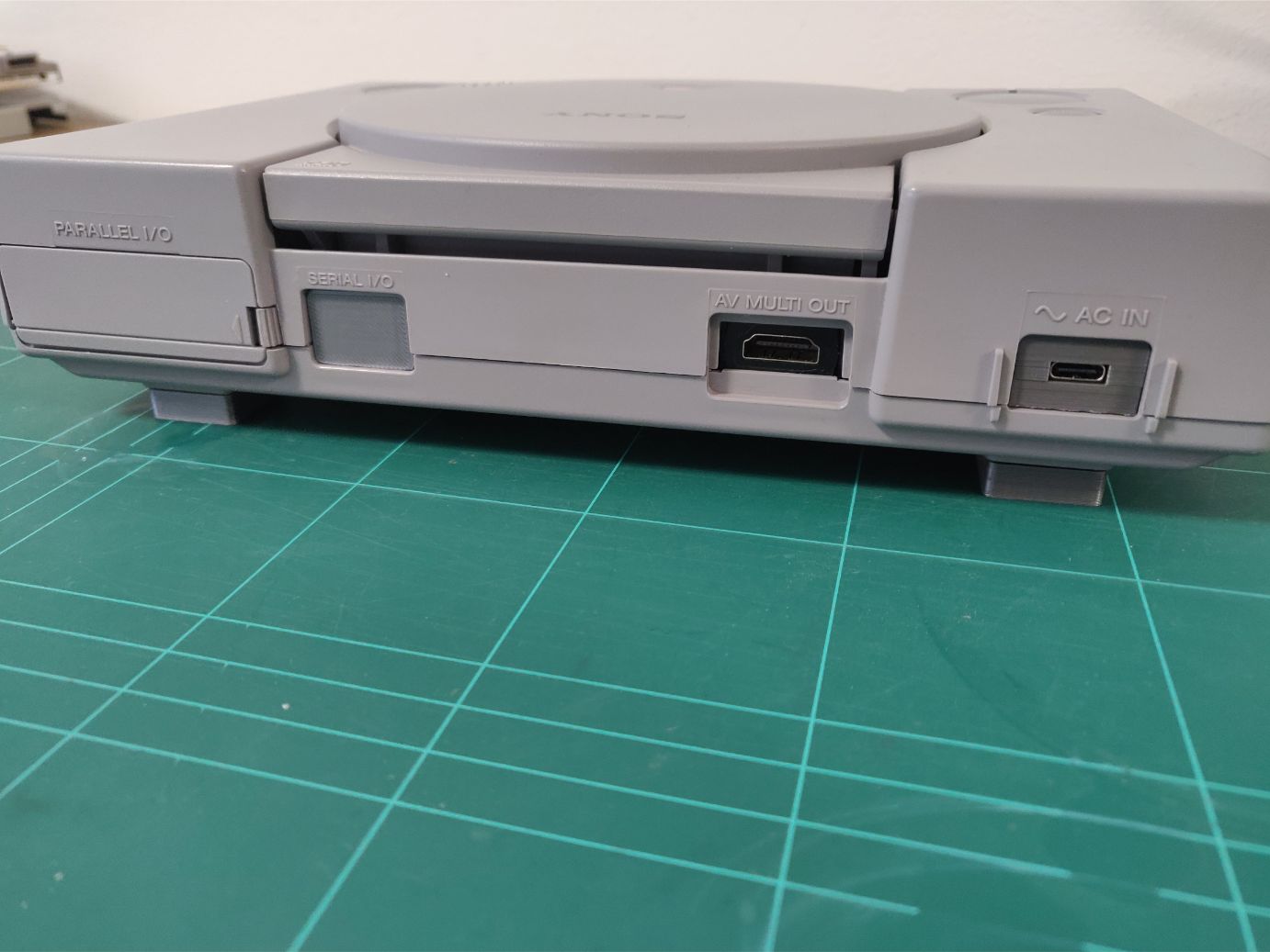
I placed them in the same positions as used by the PS1 so the labels on the case still make sense. The parallel port is glued shut and the serial i/o has a printed cover.
Test mount!
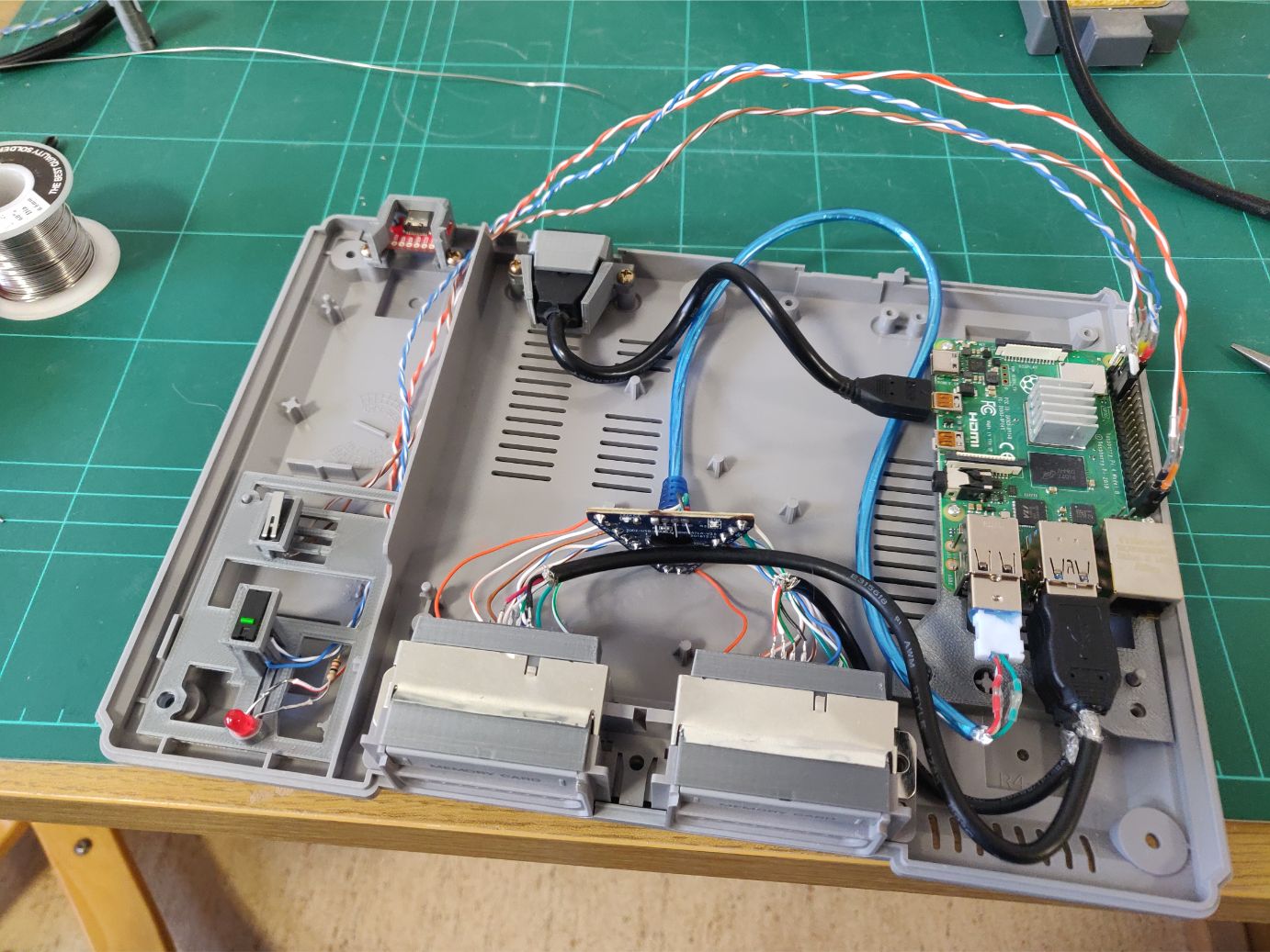
It was time to test-mount everything and see how it fits together. The USB-cables going into the RPi are a bit tight, I cut off the superfluous plastic off the controller cable to make it bend more easily.
The HDMI cable is a bit stiff so it was tricky to get it to fit.
At this point I was a bit worried because I had planned on installing an 80mm fan in the middle of the case. It would definitely be a tight fit.
Running things
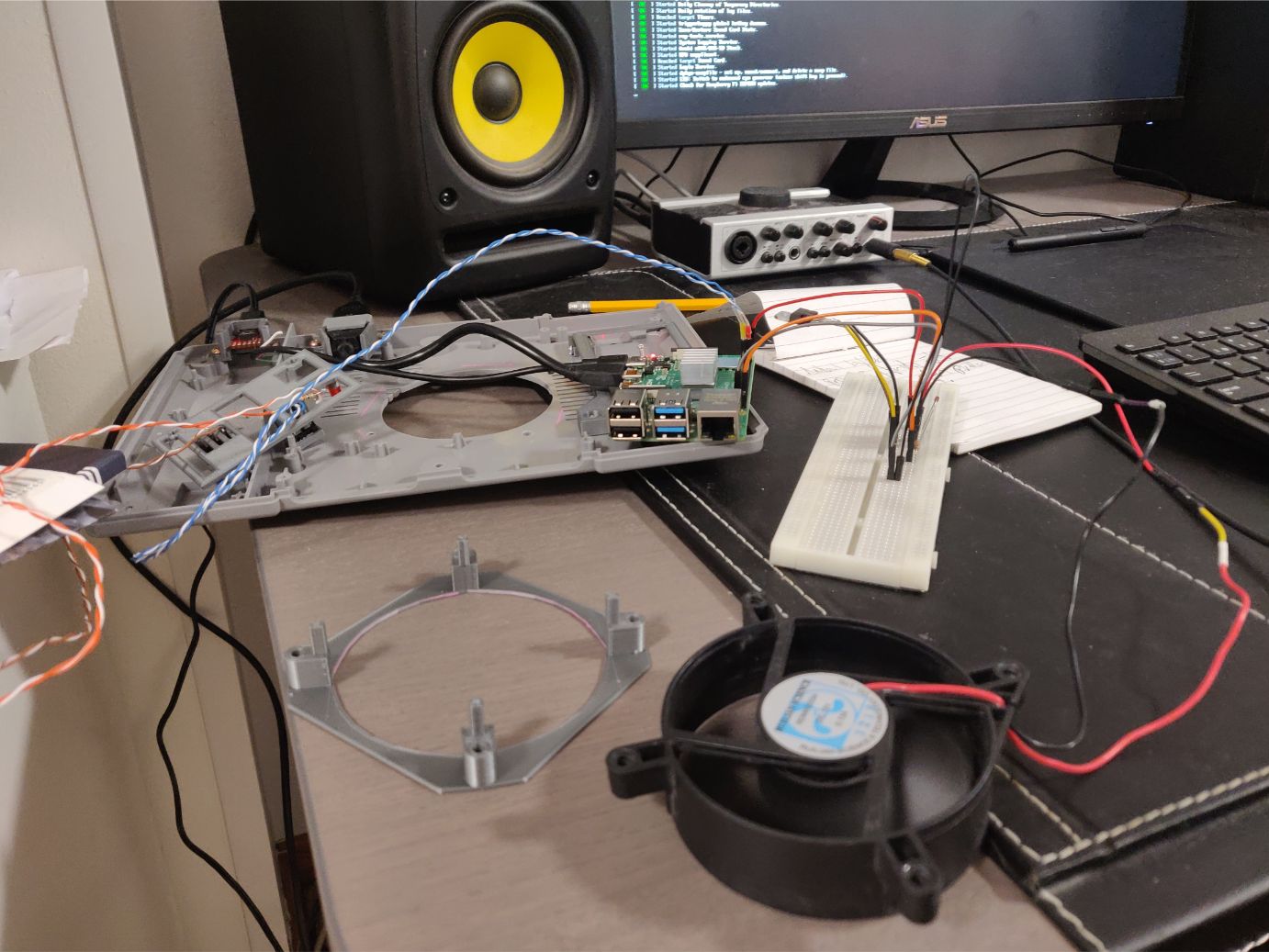
Before this image I had already started setting up Retropie and testing things out. As the RPi 4 is still pretty new there is no official build of Retropie, instead I had to build from source using an RPi4 branch.
Turns out not everything is working correctly in that branch yet. PS1 emulation seems to work but the splashcreen settings won’t start and I could not get PS4 controllers to work over Bluetooth.
Because even though it’s supposed to be close to a PS1 I wanted to add some nice new modern features, like support for PS4 controllers (which my brother has).
PS4 controllers do work over cable using the USB ports but I’m hoping the official RPi4 release will solve my Bluetooth issues.
Keeping it cool
The fan (seen in the previous image) is actually a 12V fan running on 5V through the GPIO 5V pin. Turns out that the 5V pin does not stop supplying power when the RPi is in powered down mode, so the fan keeps on spinning.
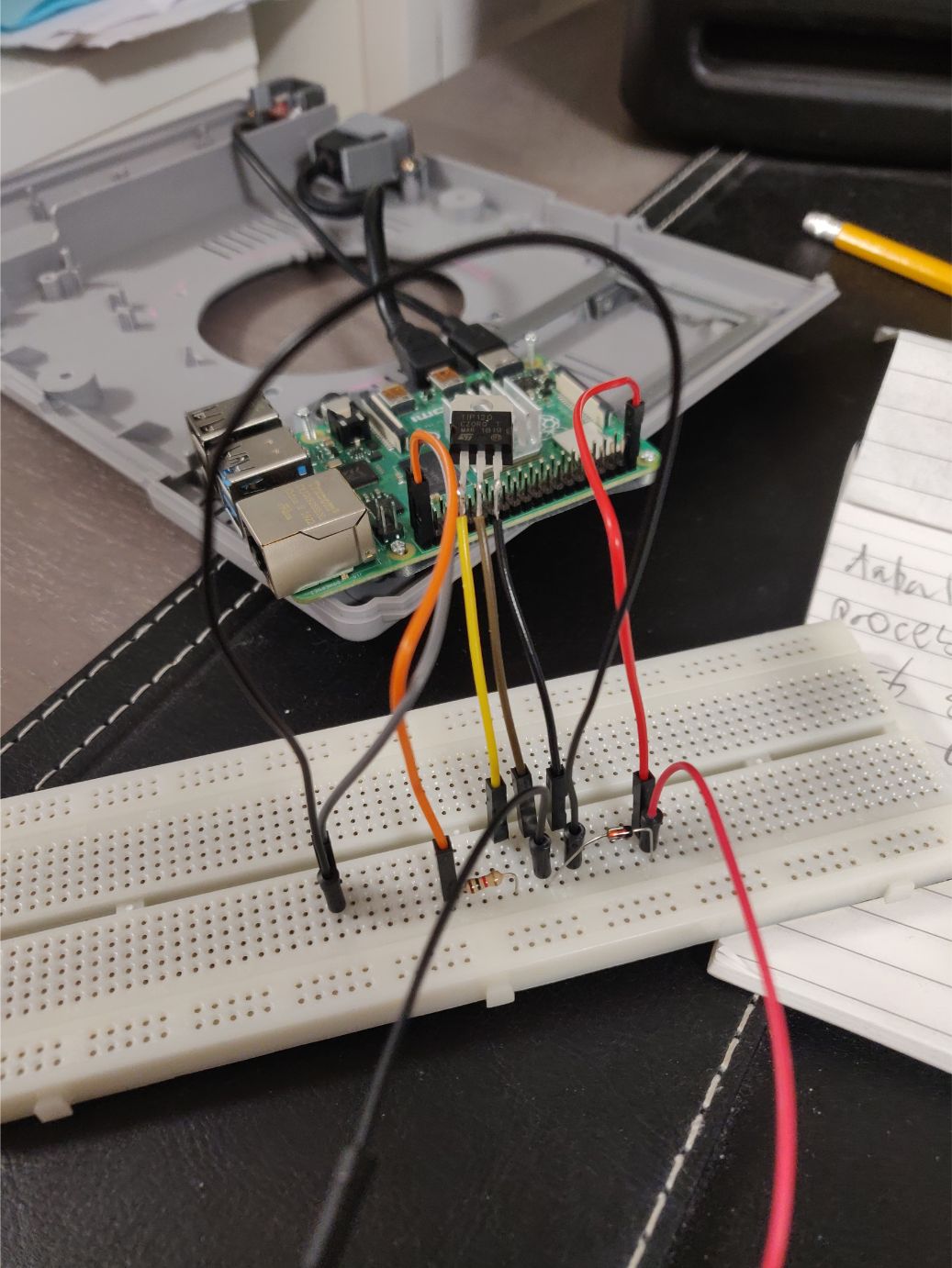
I was unhappy with this and I wasn’t the only one. I was able to find this great thread on how to use a transistor to turn on the fan using one of the programmable GPIO pins.
I didn’t have access to the same parts in this excellent schematic but I substituted the transistor and diode for similar ones.
Then I just activate the GPIO pin when the machine starts and the fan turns on. Powering off deactivates the pin and the fan stops. Perfect!
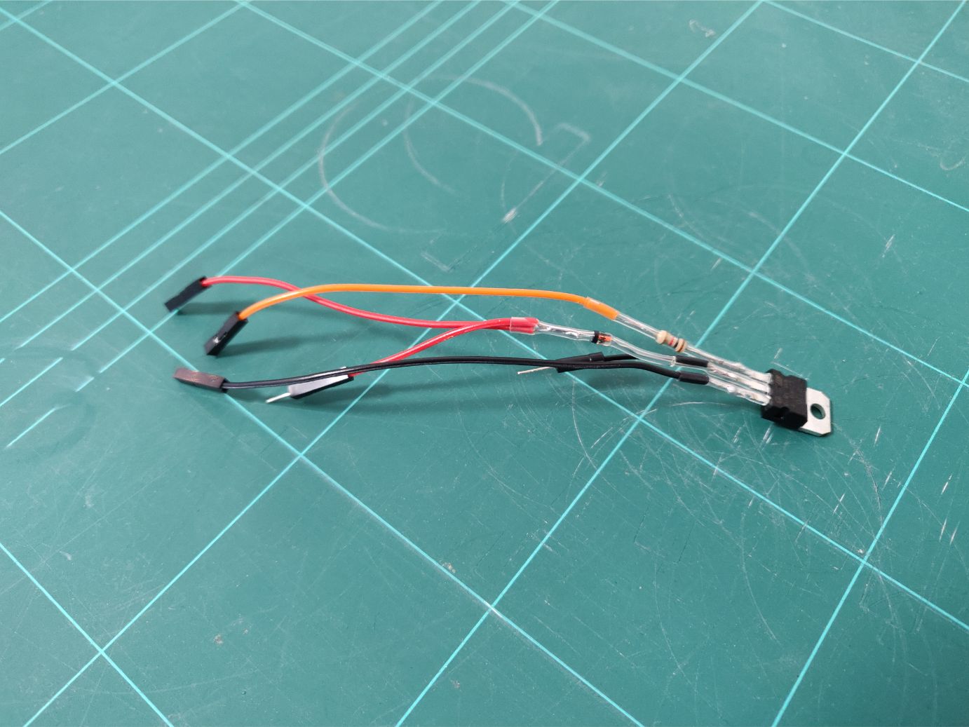
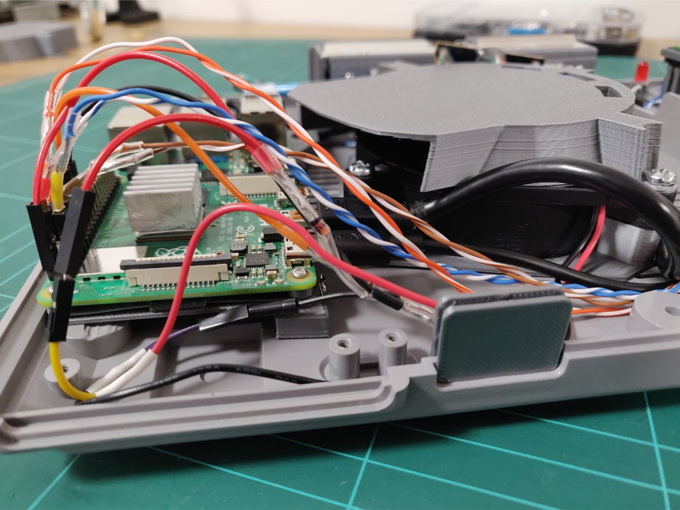
A breadboard obviously couldn’t fit in the case so I just connected everything directly to eachother like this, with heatshrink to keep things from shorting out.
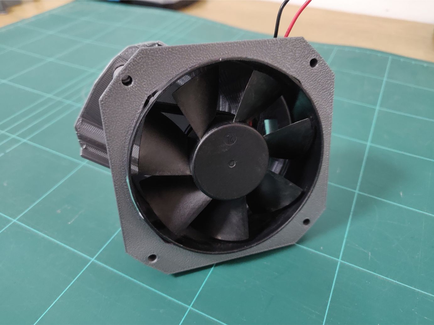
To place the fan I had to make a mount to fit to the case. To get some extra vertical space I made the fan go through the case to sit flush against the bottom.
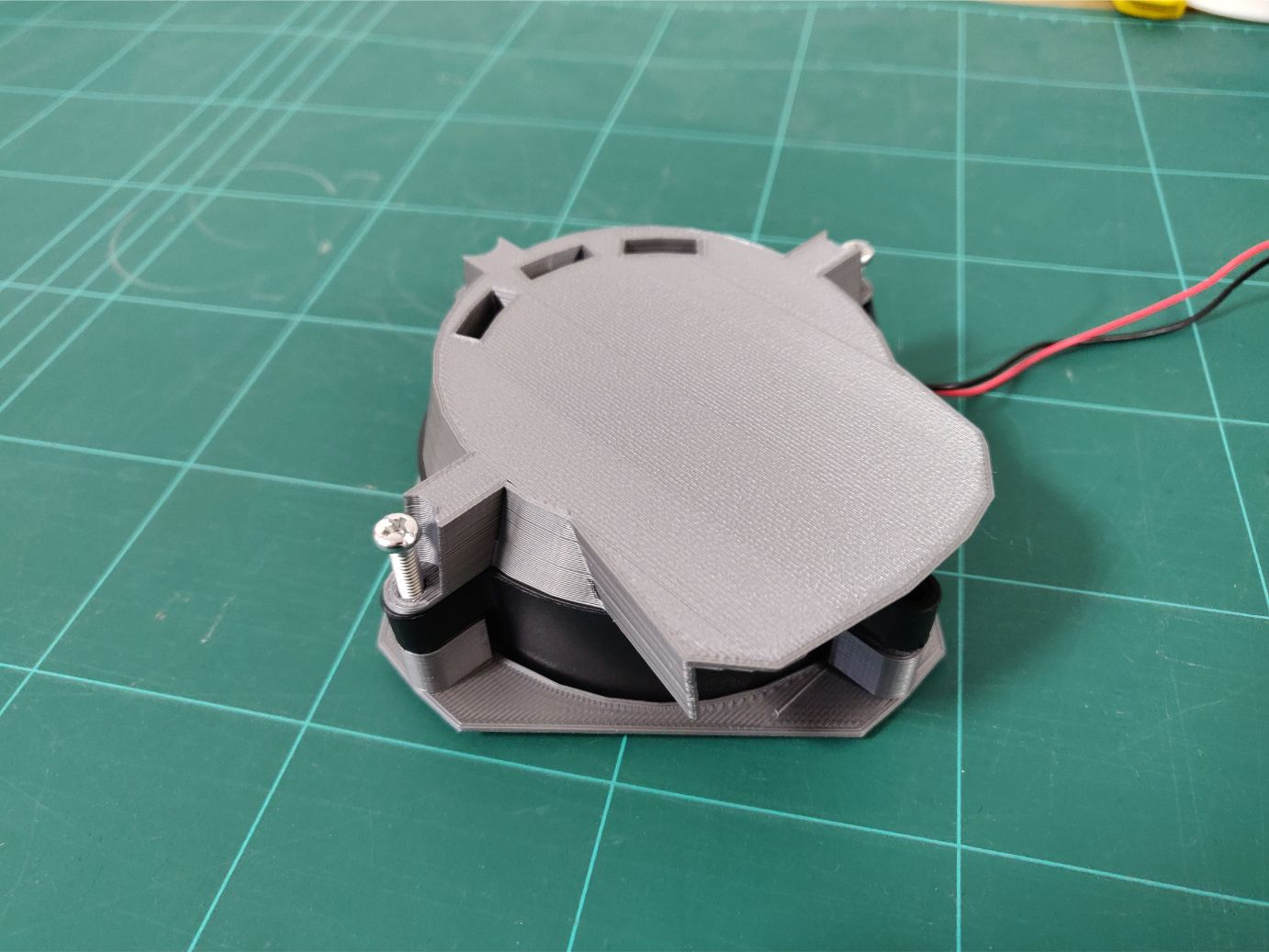
You might have already thought, “but this fan would just blow upwards into the case if mounted to the bottom”. Well spotted, that’s why I created this shroud with an opening to one side where the RPi is.
Inside the shroud I put a smooth bevel to make the air follow the top and out the side. Though I was thinking that this tight space could probably create a higher pressure (since the air redirect angle is steep) so to alleviate I added small openings in the back.
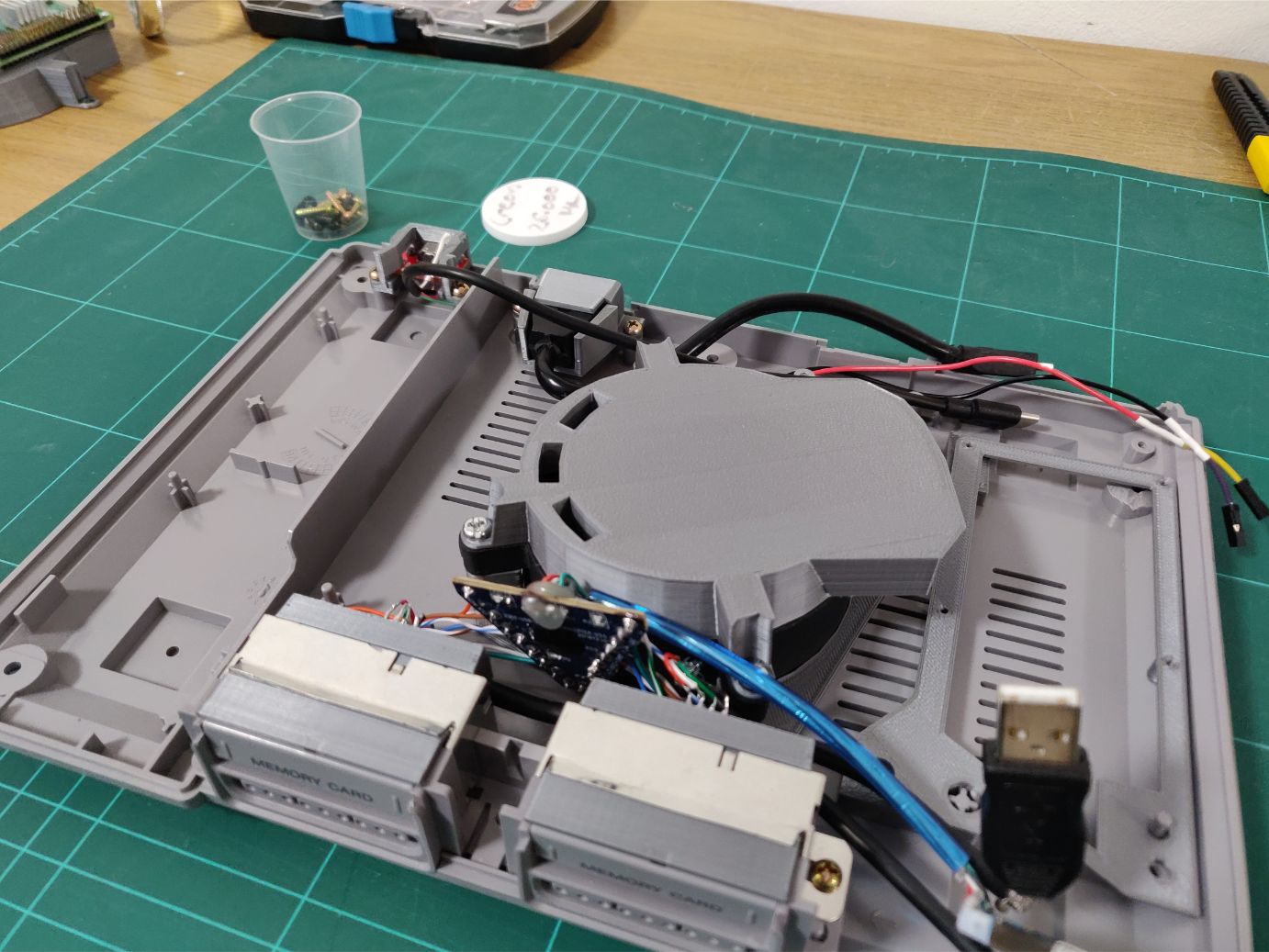
As I mentioned, it’s a tight fit but it works! I really hade to squeeze things to fit.
And it’s an even tighter fit at the top of the case, absolutely perfect!
Drive cover
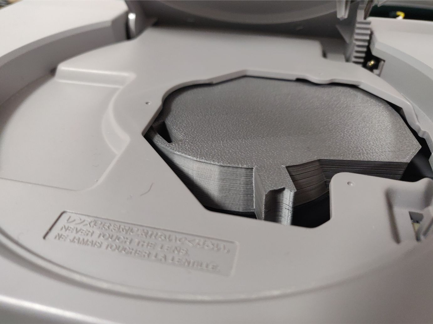
I designed a drive cover to isolate the inside and make it look a bit nicer.
At the start of the project I really wanted to fit an NFC/RFID reader here and then create fake CDs with NFC/RFID-tags. These would be identified by tag and the corresponding game would be started by the system.
A replication of the disc drive essentially. But there wasn’t enough time and I had to agree with my friend who thought it was a bit gimmicky. Still, I like the idea.
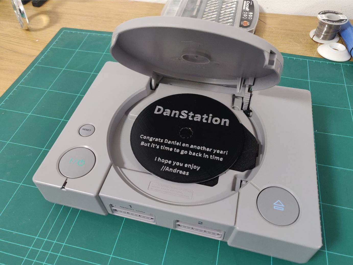
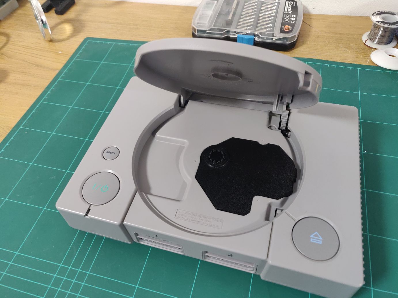
Instead of the NFC/RFID system I added the fake disc you see above with a birthday message. Having a disc like that let me just giftwrap the disc and give it to him at first. That way he had to figure out what it was before finding the console.
Putting it all together
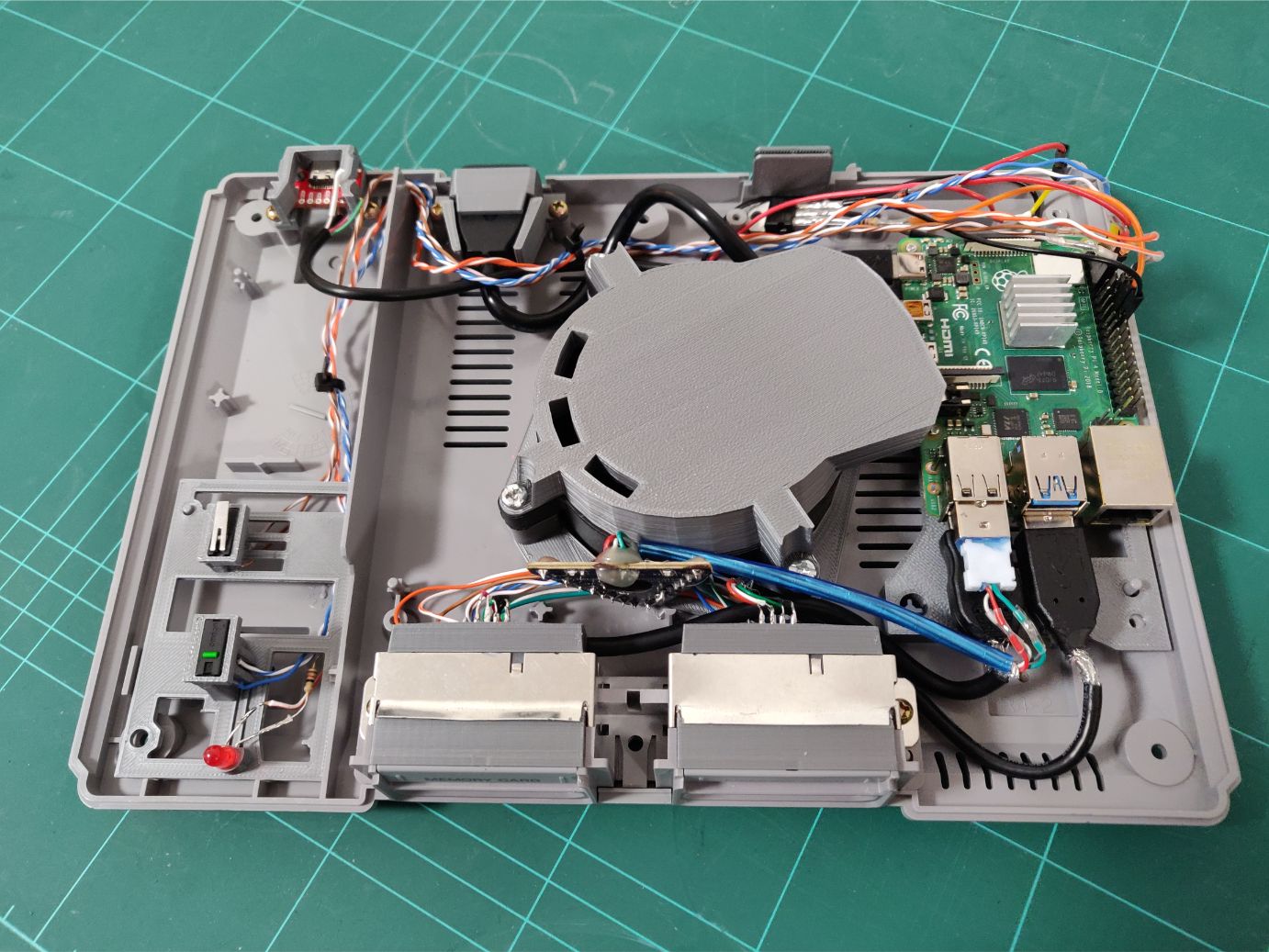
A final picture of everything mounted together in the case. Note how tight it is between the fan and PS1 controller circuit.
Here you can see how I reused the screw holes and other mounts to make the power/reset/LED sit well without having to add new screw holes or glue anything.
All the GPIO connections to power & reset buttons, power LED, fan circuit and fan. You can also see the ventilation exhaust pointing towards the RPi.
The feet
I noticed an issue after putting everything together and testing it: the fan doesn’t push a lot of air. Part of that is the fact that it’s only running at 5V but I noticed a big difference if I elevated the case.
So I printed feet extenders to lift the case a little bit higher and it seemed to help a bunch.
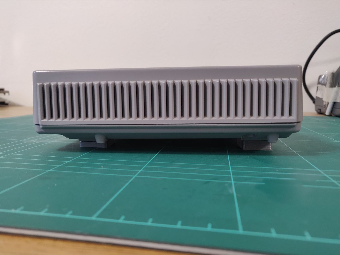
I actually made the back feet a little bit taller. Mostly you see the case from the front anyway and this way I could both increase the airflow without making the front legs look too tall.
And this way the top of the case is a little bit more visible which is a win in my book, I want to show off both the front and top.
Completion
Finished and ready to game!
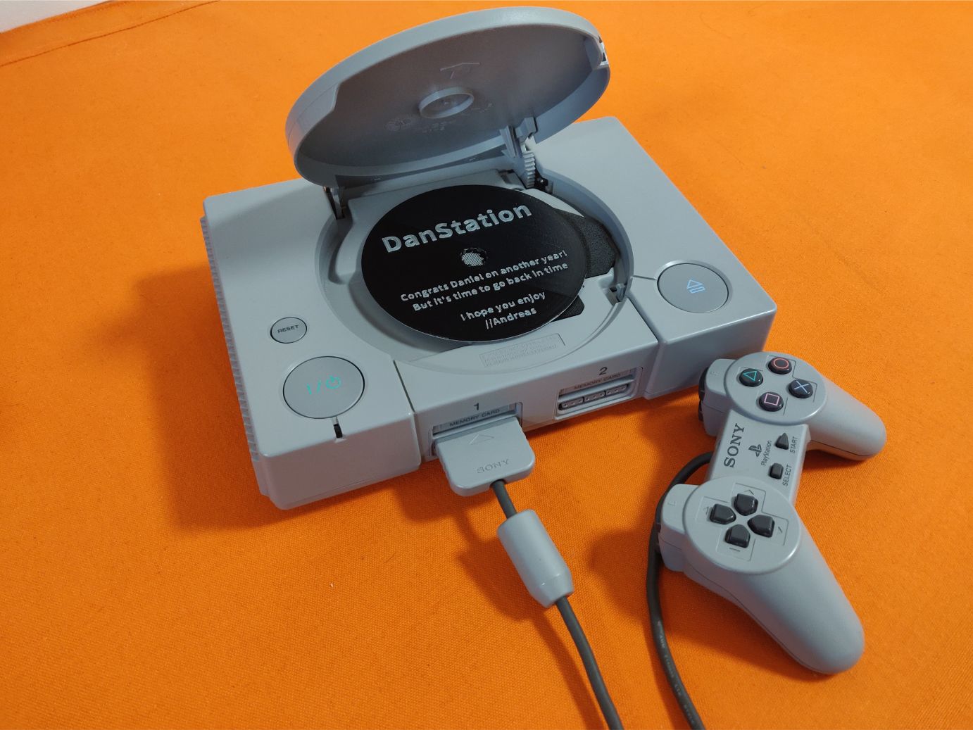
Once again, finished and showing off the gift disc.
I’m very happy with the result, I actually got pretty much everything I wanted to get done to actually get done! It both looks great and works well. And somethings will only improve when Retropie releases a version that officially supports the RPi 4.
It was fun doing a project that required that many different skills, switching between them all the time. With this I got to do design, 3D printing, electronics and setting up Retropie (and a bunch of tweaking).
The design files are available online at Thingiverse if you’re interested in making your own.
So thanks for reading all the way to the end! If you have any questions or comments, just contact me using the buttons at the bottom of the page.
Bonus image
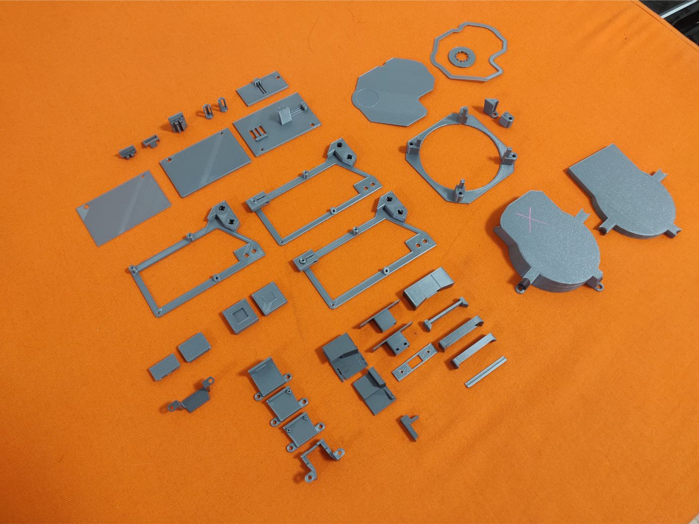
A bonus image showing all the discarded iterations of parts I designed and printed. Most things took a few iterations to verify that my measurements were correct and that the design actually worked. Then usually it took a few more to make it work well.