During the last year I’ve been working on and off on a dream project of mine: building my own computer case. Since I’ve been a teenager I dreamed of building my own computer case from scratch. Several case mockups have been made over the years and once I actually set out to build one but that case was never finished.
In 2021 I felt like it was time to go back to a stationary computer instead of using my laptop as my main machine at home. The laptop was pretty loud, ran incredibly hot and was starting to lack in performance (often because of the previous two points). Additionally, the laptop was never really moved and was always plugged into an external GPU with a RTX 3070 to get a little bit more graphics performance.
So a stationary computer made much more sense. Before even starting with the design I came up with a few requirements for the case. It should be:
- High performance
- Silent & low temperature
- Air cooled
- Easy to open & work in
- A clean visual design & a small floor/desk footprint
Before going into the creation, lets just summarize the parts that were used for this build.
Computer parts
CPU: AMD Ryzen 9 5900X
GPU: MSI RTX 3070 Ventus 3X
MB: ASUS STRIX B550-I Gaming
PSU: Corsair SF600 600W
RAM: Kingston 32GB DDR4 3600MHz CL18 Fury
HDD: Adata XPG SX8200 Pro 2TB
CPU-cooler: Noctua NH-U12P SE2
Exhaust fan: Noctua NF-A20 200mm
Case parts
Inner frame: MakerBeam 10x10 profile beams
Outer case: Clas Ohlson black PLA; filled, sanded & sprayed matt black
Wood sides: lasercut oak veneered plywood & black oak MDF from Cotter
So lets get on with the build! (or just jump to the photoshoot if you want to see the finished case, I won’t judge!)
Design
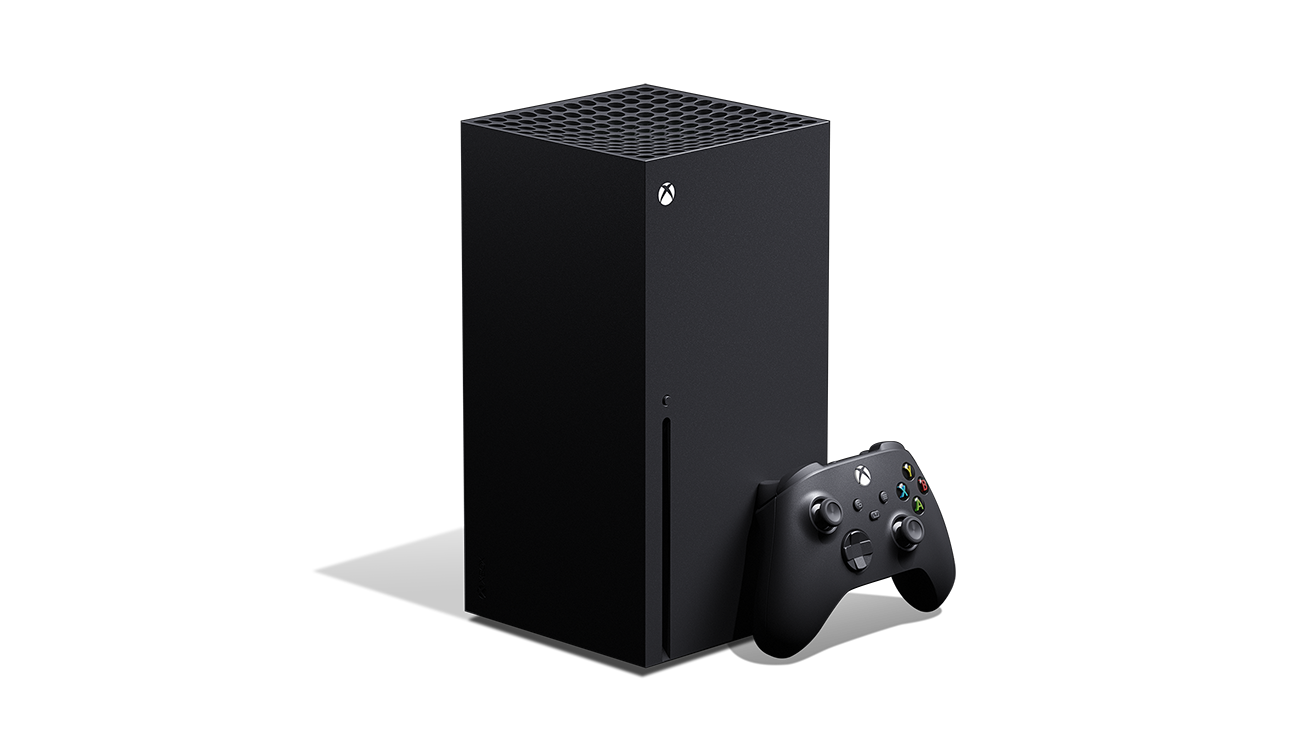
Since it was first announced I’ve been a fan of the Xbox Series X design, I love the boxy shape and vertical format. Not only does it look nice but it also has a small floor/table footprint.
There are vertical cases out there already but most of them aren’t square and often rely on watercooling. I’m not much for watercooling as it feels fiddlier and less reliable than air cooling, not to mention that I had an old great Noctua cooler that I wanted to reuse. I also wanted a case where the cables came out from the bottom instead of from the back, that way I could have the case pushed up closer against the wall.
For this case design a small size was preferred but never the top priority, I didn’t want to compromise on the above requirements for the sake of size.
Airflow
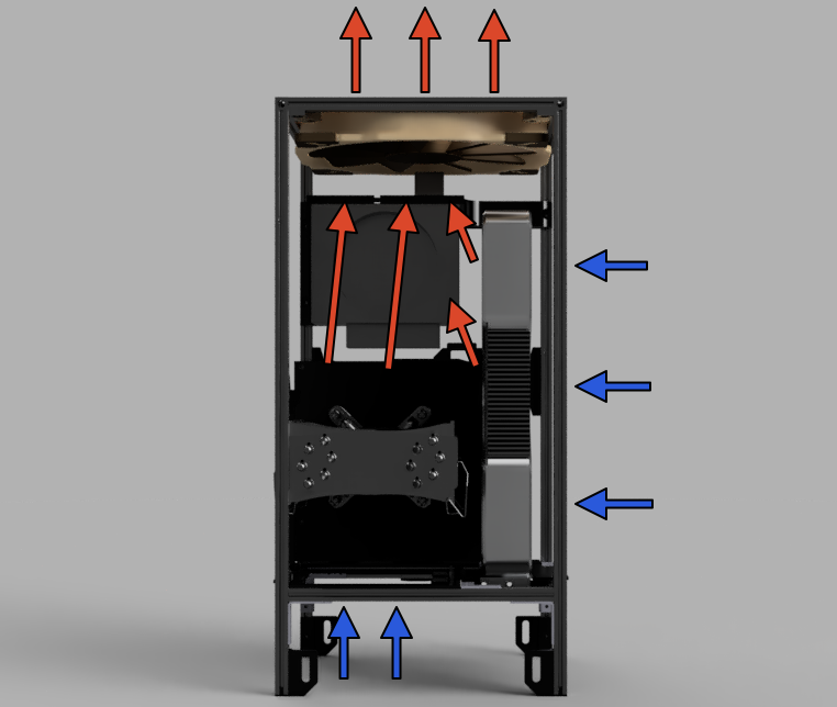
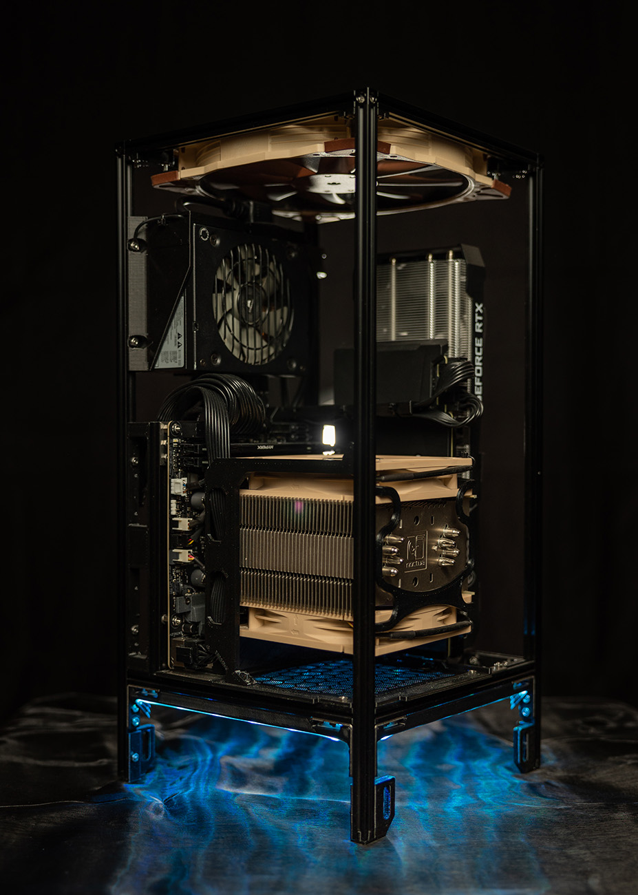
Speaking of airflow, one design element I wanted to incorporate was a clear airflow path through the case; many small formfactor cases I’ve seen put case airflow far down the priority list. They usually just pull fresh air from the outside but have no consideration for where that warm air is supposed to go. So I took a page from the Xbox Series X which uses a top vent; I designed my case to pull air from the bottom (for the CPU) and from the side of the case (GPU) and then push it out through the top using a large 200mm fan.
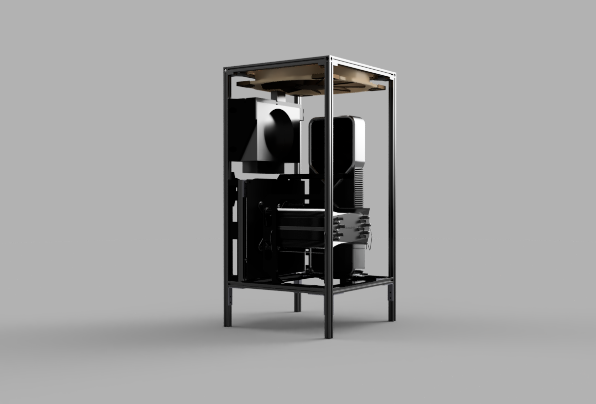
A case in two parts
To give the case a clean exterior but still make the case easy to open and work in I designed the case to actually be in two parts. One part is the inner frame where all the computer hardware is mounted. The second is the outer case which holds the outer wood panels and the top fan grill. The outer case would then just slide down on top of the inner frame and cover it.
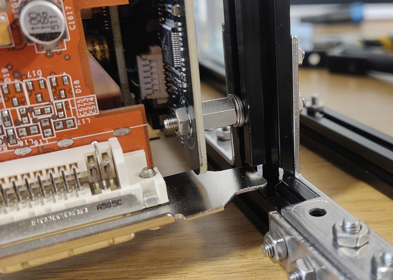
I had to work hard to ensure that all the parts in the inner frame would not extend outside the frame, potentially colliding with the outer case when mounted. In a few places this caused some issues, like one edge of the motherboard and the CPU-power connector extended past the frame, which forced me to expand the dimensions somewhat.
I also tried to keep the outer case as simple as possible, avoiding anything that would require a connection between the inner frame and the outer case. Having to disconnect something between the two would when removing the outer case be frustrating.
Creating the 3D model
Early on I did a quick mockup for the outer case in Blender to get the feeling for the form factor, shape and design. You’ll see that the shape actually came pretty close to the final result.
For months I sat in Fusion 360 and designed all the parts. I tried to include as many things as possible in the model file since since that makes it easier to ensure that things will actually fit later on. Though I had to use more generic/similar computer parts since I couldn’t find any models for the specific parts I had.
Most 3D printed parts took multiple iterations to get right, with so many test prints. In a few cases the designs didn’t work at all and required complete redesigns.
Now lets move on to the build!
Building the inner frame
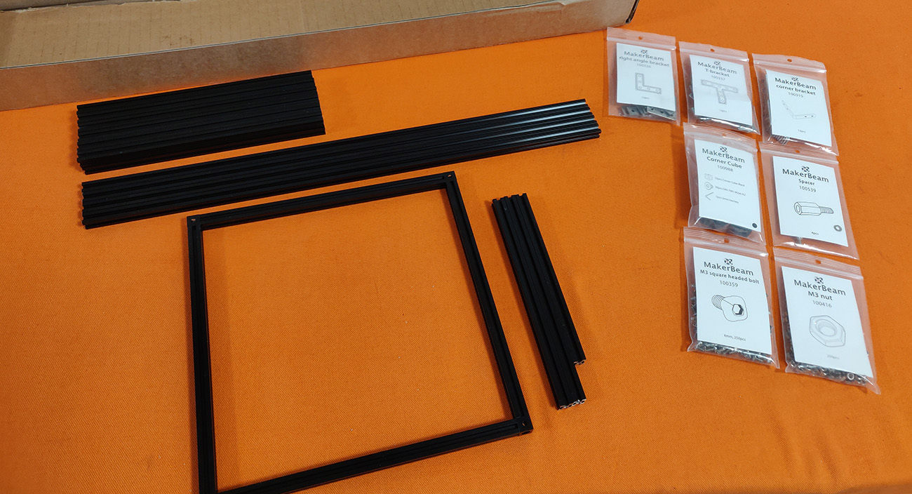
For the inner frame I decided to use Makerbeam 10x10mm beams, after having seen others create amazing cases with those. Pulling the gun on the order was a bit scary as it was somewhat costly and I was afraid that I would have incorrectly measured something in my design.
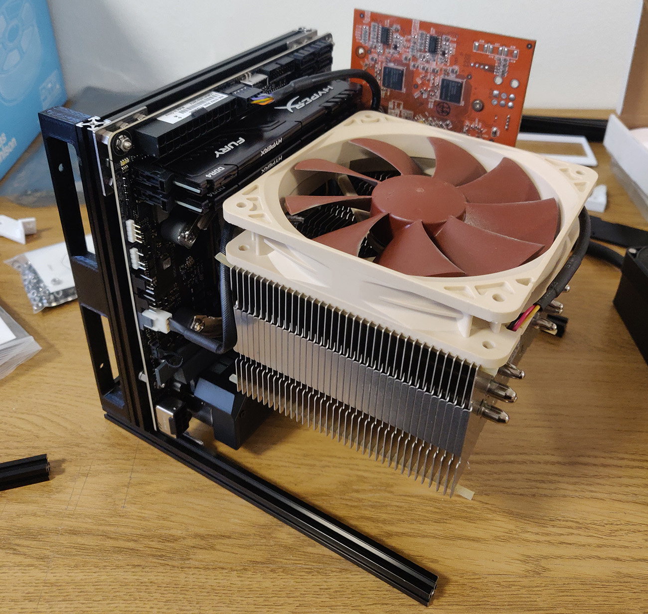
I tested out mounting the motherboard on to the beams with CPU, CPU-cooler, memory and an old graphics card. I found that with my design there was a little bit of sag on the motherboard frame from the weight of the CPU-cooler. So I designed a bracket (visible on the left side) that will help support the motherboard frame from the full inner frame later on.
As it turns out, the GPU PCI bracket is a bit longer than I’d hoped so I had to get my Dremel out to chop off a little from the beam to get the bracket to fit.
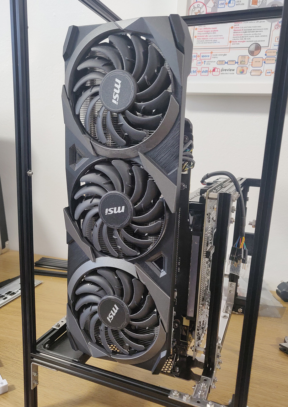
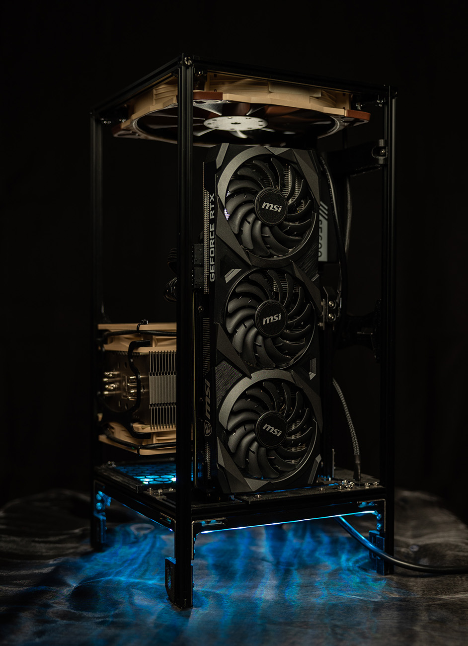
To ensure that everything would fit correctly I tested it out with my RTX 3070. It’s a pretty beefy card, so it only has a few centimeters of space up to the top fan. It took quite a few iterations to get the GPU support bracket to fit nicely with the graphics card (bottom left of the graphics card).
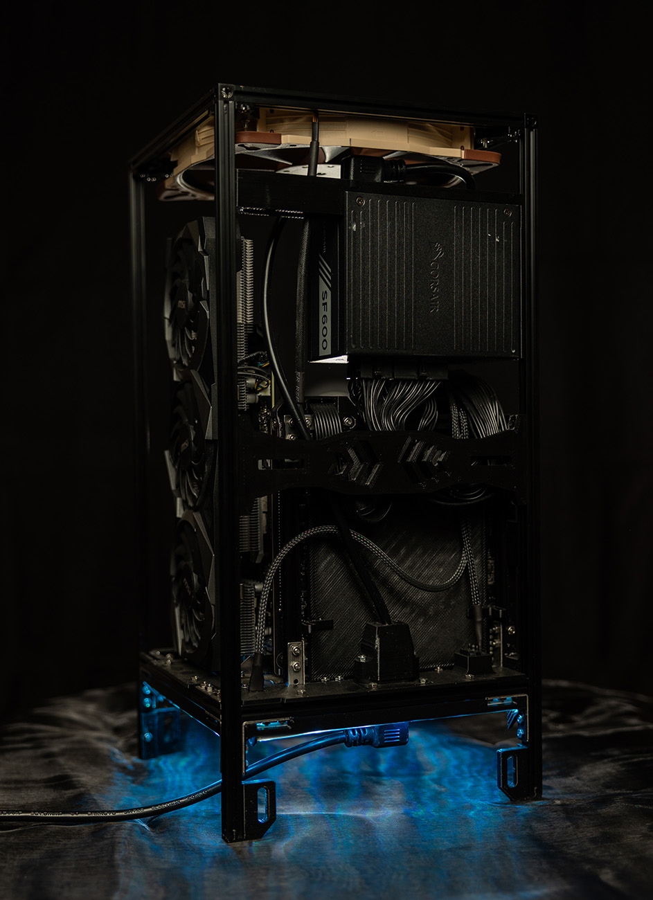
Cable management
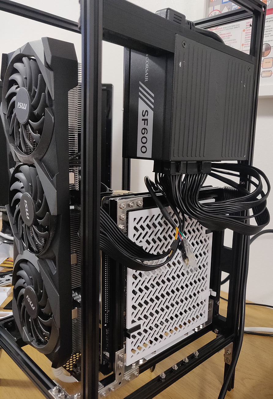
To hide all the cables I figured I might as well hide them behind the motherboard, like most cases do. To keep the cables from touching the motherboard I designed a detachable plastic shield. Getting it to fit well while still being detachable created a lot more work than it was worth, I probably should have just fixed it to the frame with screws.
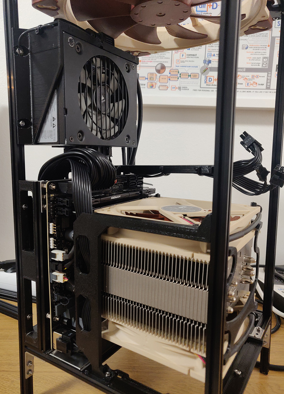
The 200mm exhaust fan really towers over all the parts. As mentioned previously it was crucial that nothing extended past the frame or it could collide with the outer case when sliding it on. To solve that I designed cable covers & routes. Note the cover for the CPU power cable to the left of the CPU cooler, it both keeps it inside the frame and also hides the cable somewhat. The PCI-E cable routing was also a great help for cable management, as they exit the route just where the GPU connectors will be.
CPU fan clips
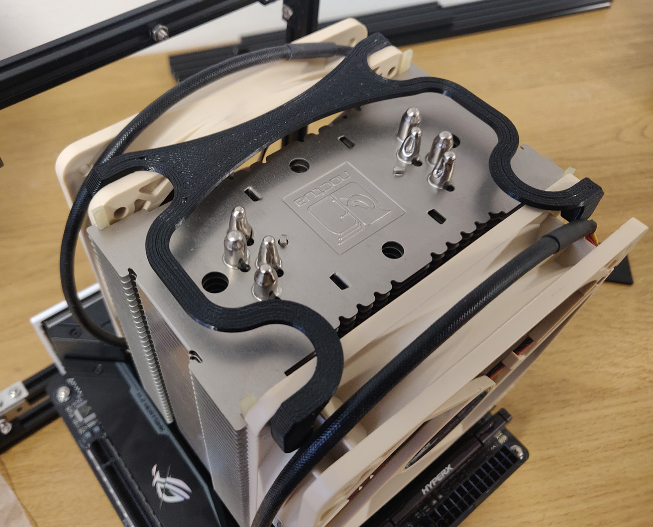
Shortly after test-mounting the computer parts I found out that the fan clips for the CPU fan extend out too far and would hit the outer case. So instead I created my own semi-flexible fan clip design which turned out to fit perfectly and ensure that the fans sit snugly onto the heatsink. To make sure they could handle the heat that the CPU would generate I printed them in ABS.
Fan filters
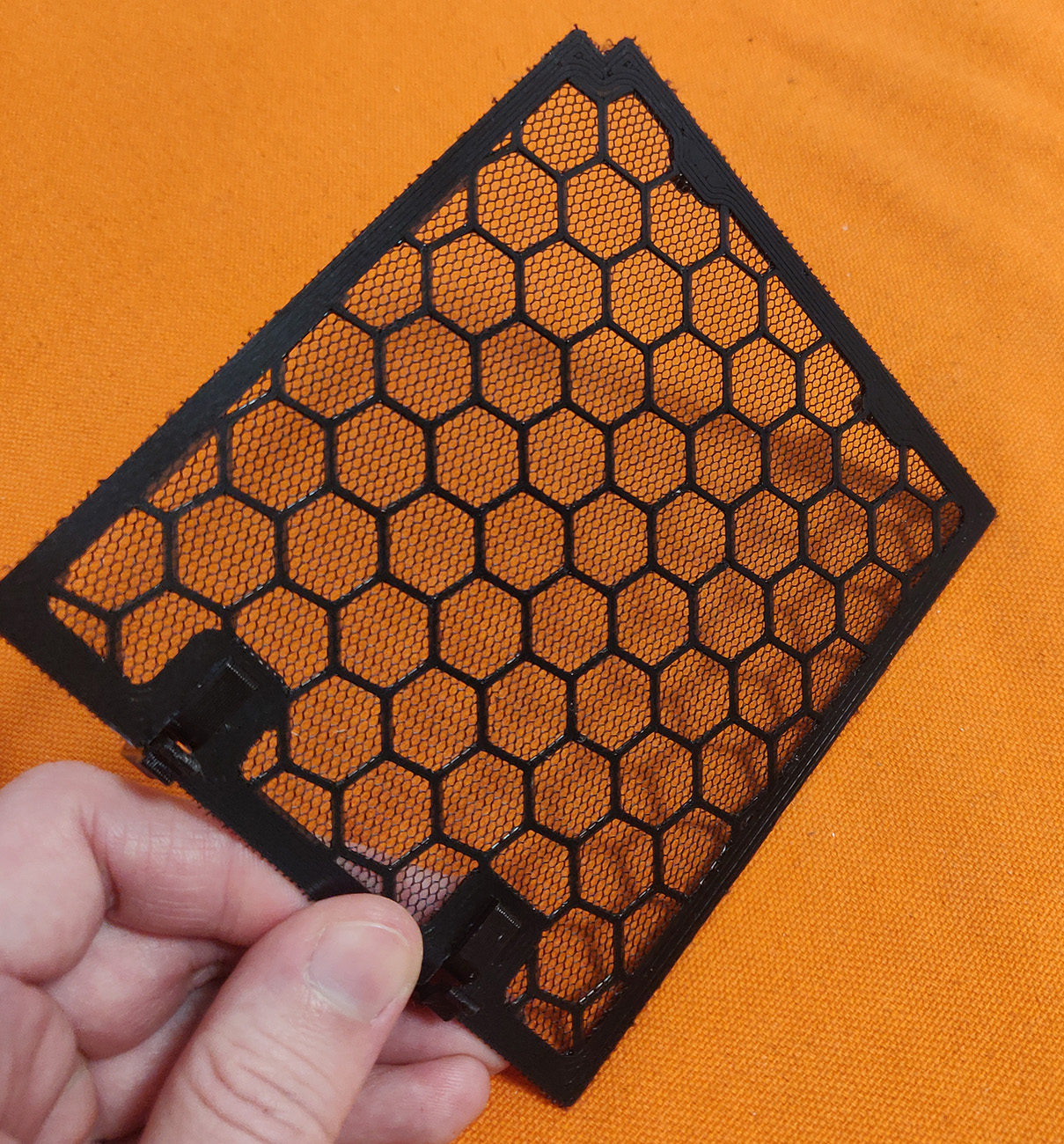
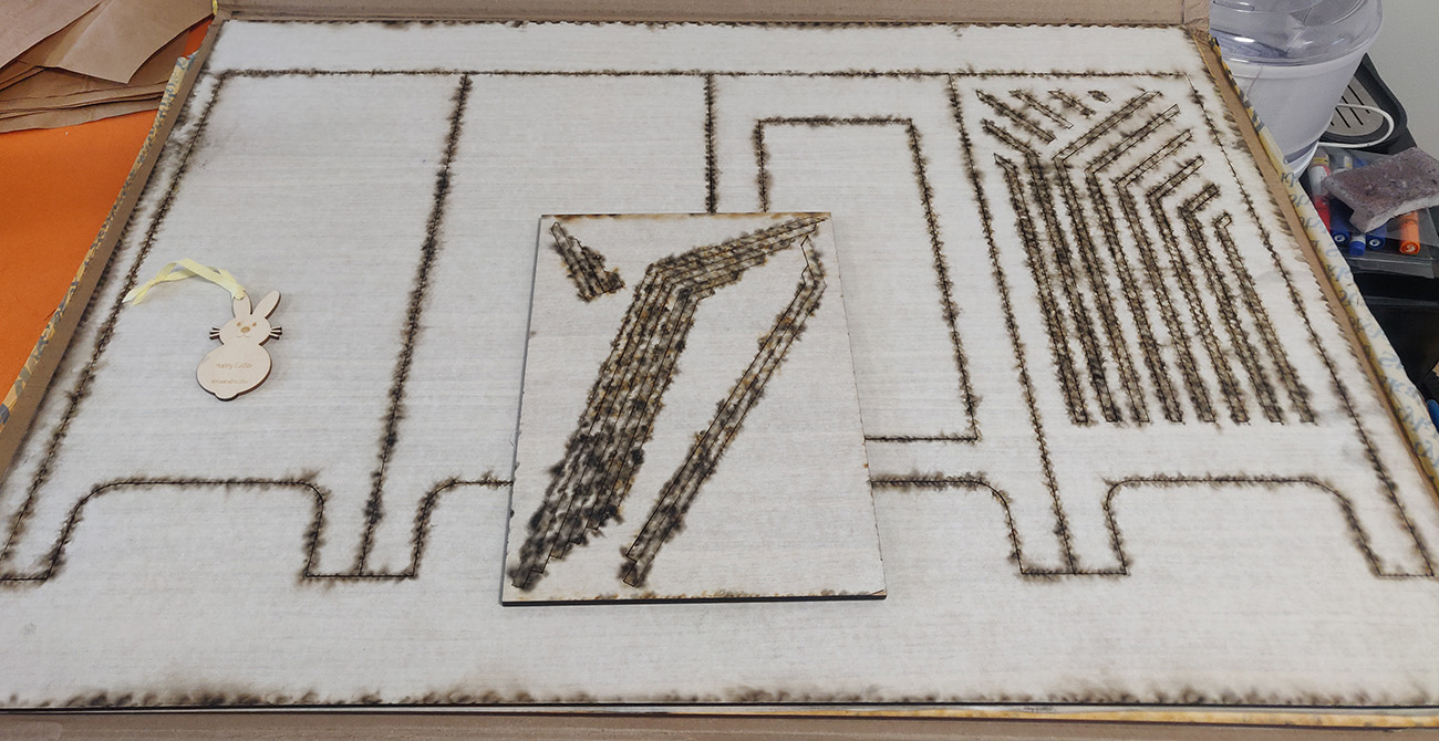
I have two cats at home so I know that their hair get absolutely everywhere, so some kind of fan filters were an absolute must. I remembered reading about 3D printing on fabric so I came up with the idea of layering in a mesh fabric into a 3D print; that way I could make filters of any shape & size. Essentially you print a few layers, pause, add the mesh and restart the print. Then you just have to trim the outside edges.
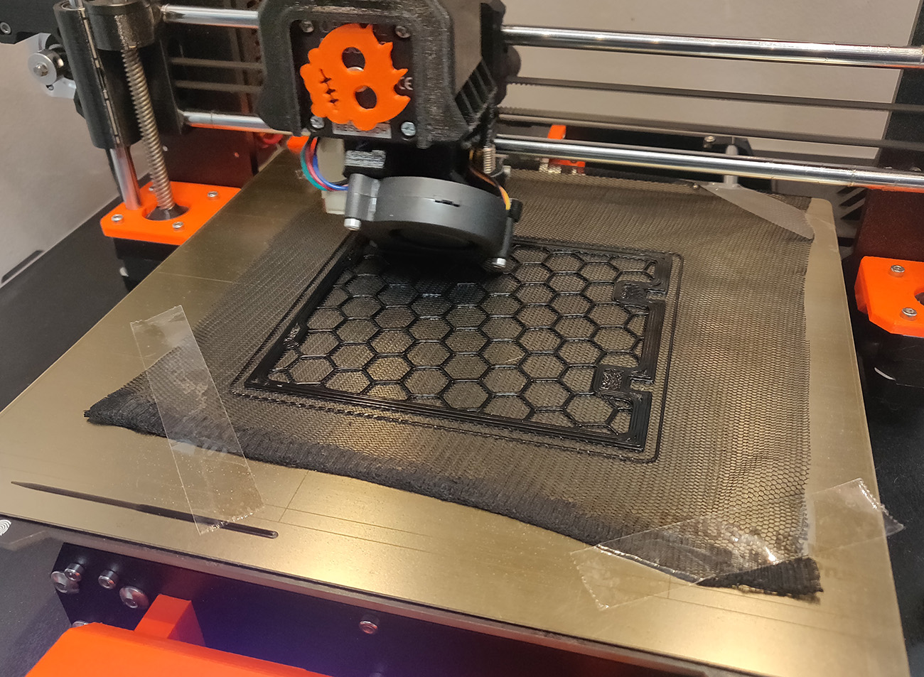
It can be a bit fiddly to add the mesh mid print. Especially if the material is stretchy since then you have to try to ensure it’s stretched the same amount in both directions.
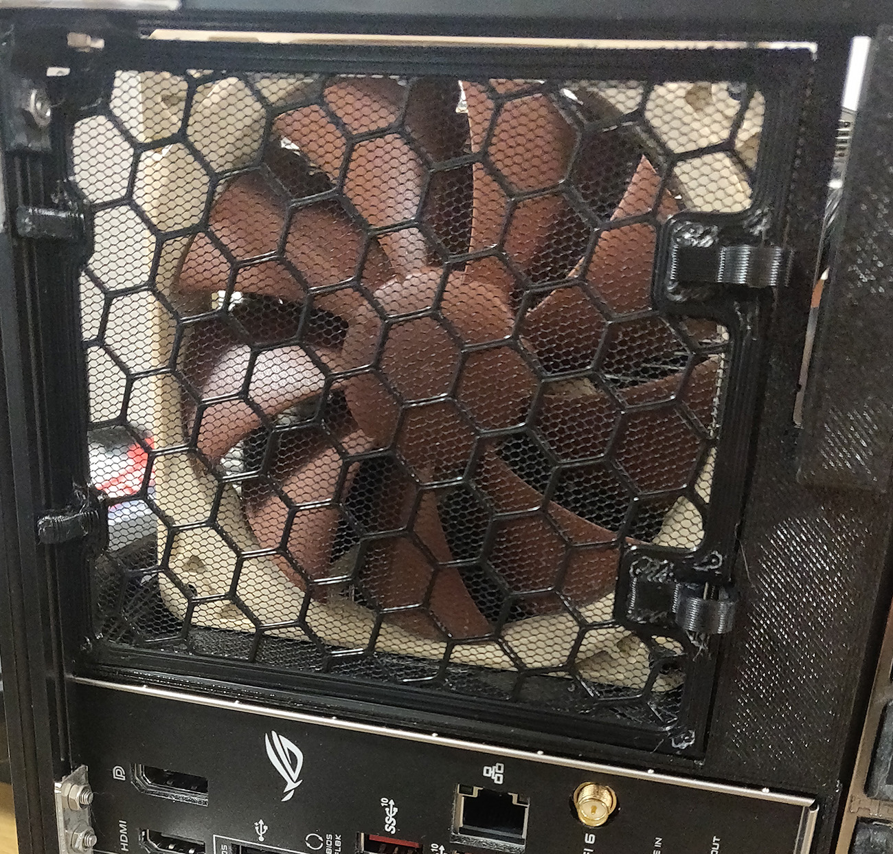
The end result is amazing and I’ve already been able to verify that the filter works quite well! I’ve also made the filter removable with two clips, I might remake this one at a later point since it doesn’t snap in place as well as I’d hoped.
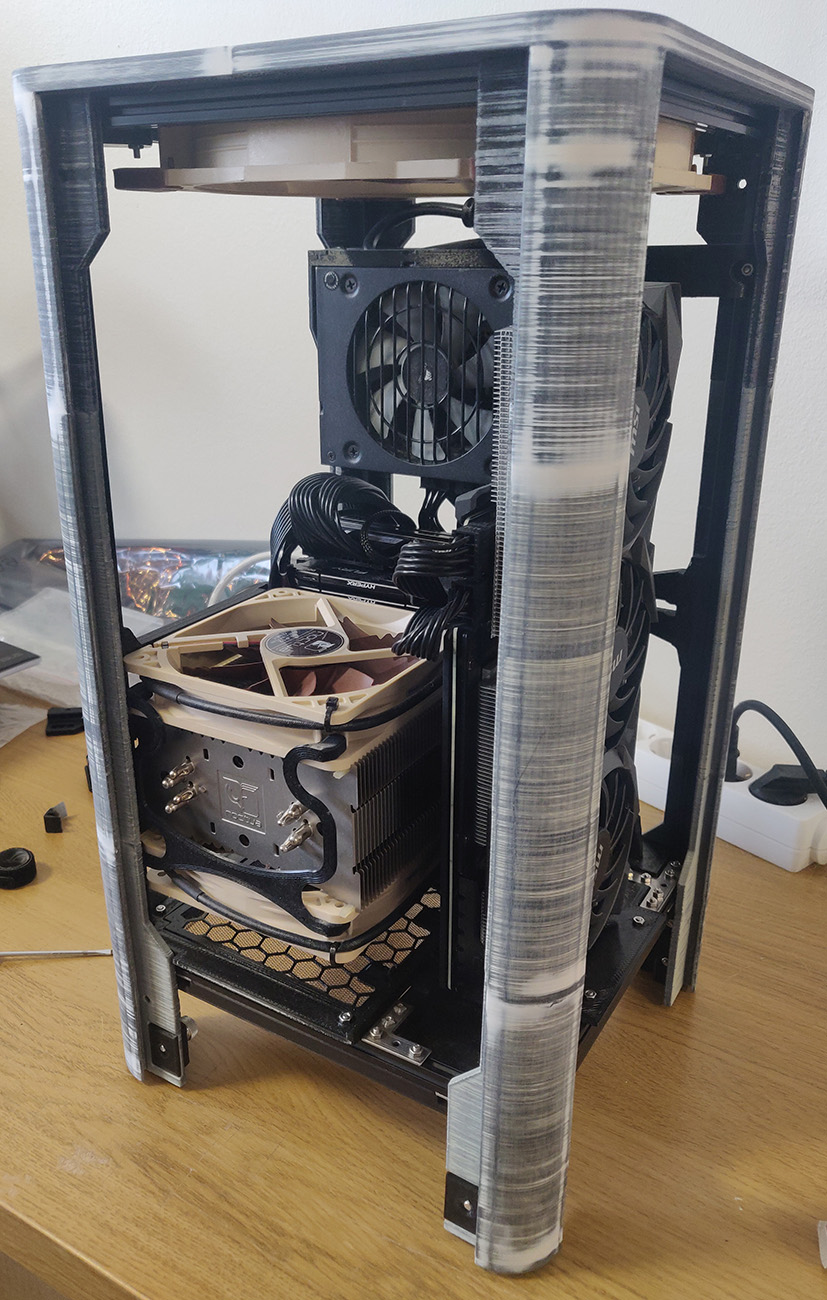
Escaping the office
So far all my work had been done at my office. Well, turns out my office mate got Corona and I was afraid that I might have been infected as well. I didn’t want to sit at home, sick, without anything to do so I brought home what I had made so far to use it a bit.
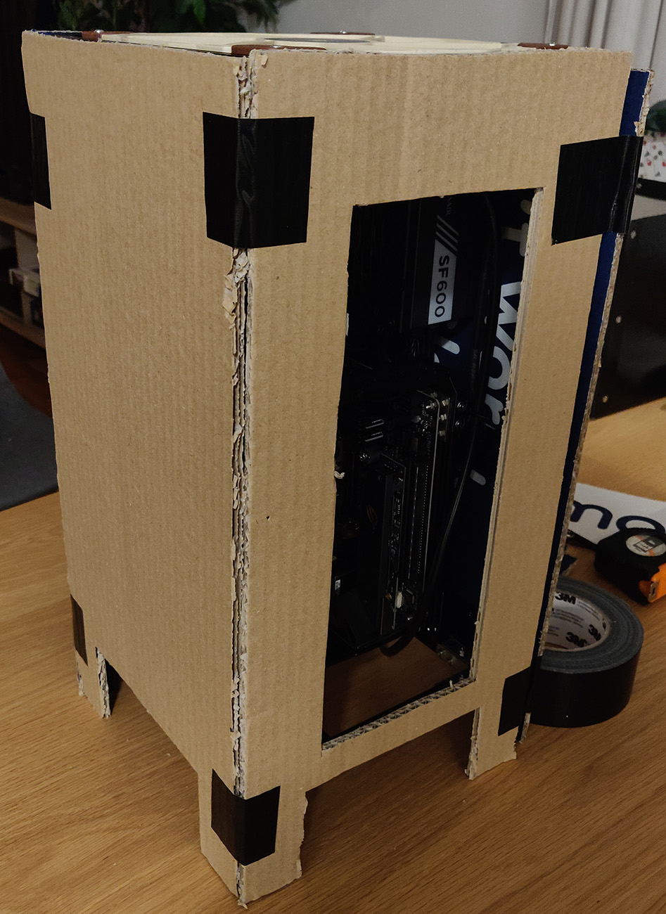
At this point it was still just a barebones frame though. I definitely didn’t want any of our cats to put their paws the fans. Cardboard to the rescue! I made this gloriously temporary and ugly cardboard version of the case; good enough for gaming from home a little while (and luckily, I didn’t get Corona).
Connectors & cables
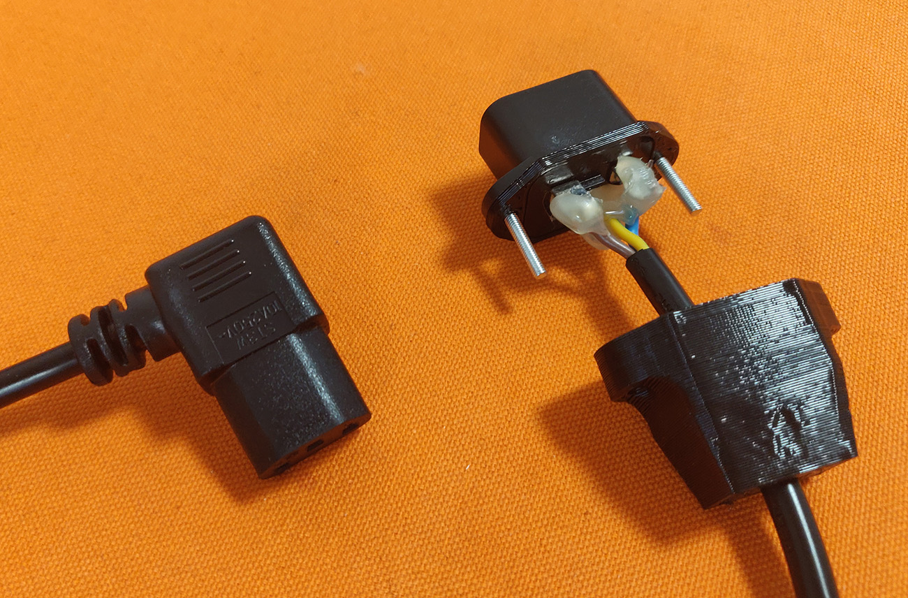
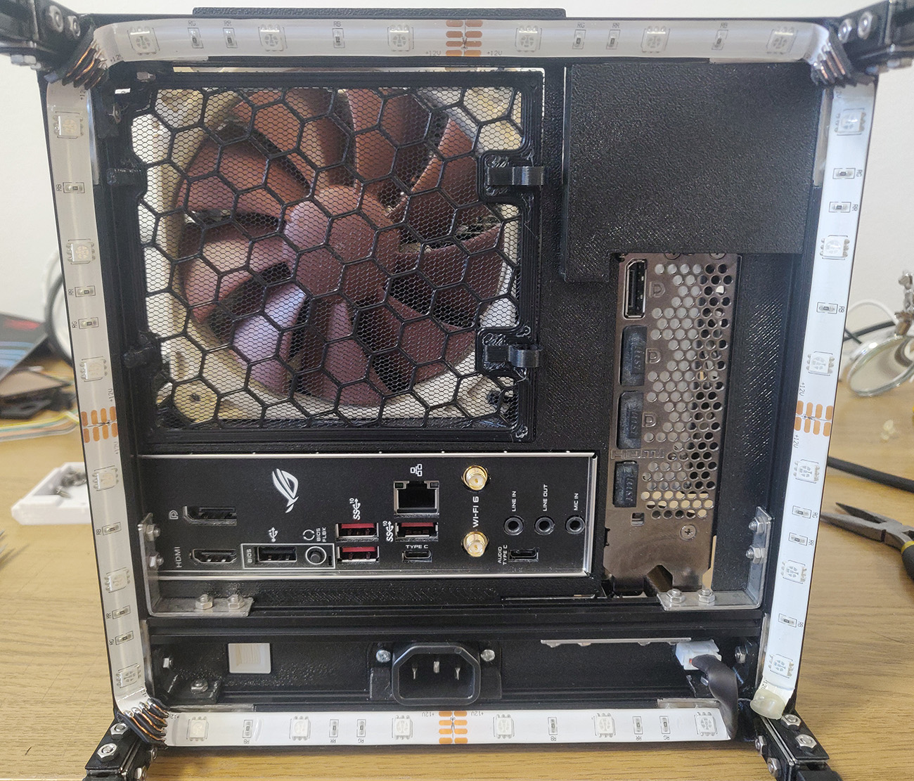
You may have noticed that the power supply is inside the case, so how do you connect the power cable? I had pondered the same thought during the design. At first I tried to find an extension cable that had an angled connector for the PSU-end. But I couldn’t find anything good online so after some trepidation about soldering a mains current connector I decided to make my own.
It turned out pretty well, I ordered the power mains connector online and designed a mounting piece for it. And to ensure there would be zero chance of getting a shock I created an outer sleeve that attaches to the connector.
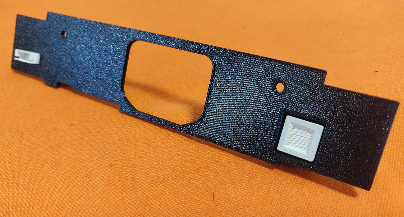
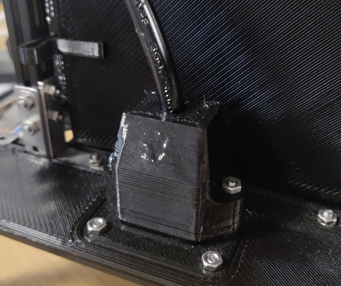
I also needed a power button to start the computer. In the first sketch I had a button that would be accessible from the front of the case. But I came to the conclusion that I rarely actually use that button, I usually just put the computer into sleep mode and start it again by using the keyboard. So why have a very prominent power button considering how seldomly I use it? So instead I hid it, I put it on the bottom, front left side of the case next to the power plug.
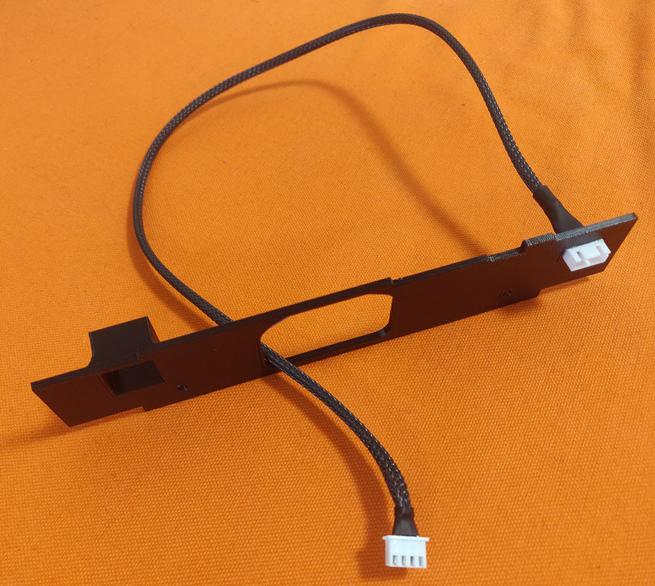
I also added a connector for another feature I hadn’t originally planned but I definitely wanted during the end of the project…
Let there be light
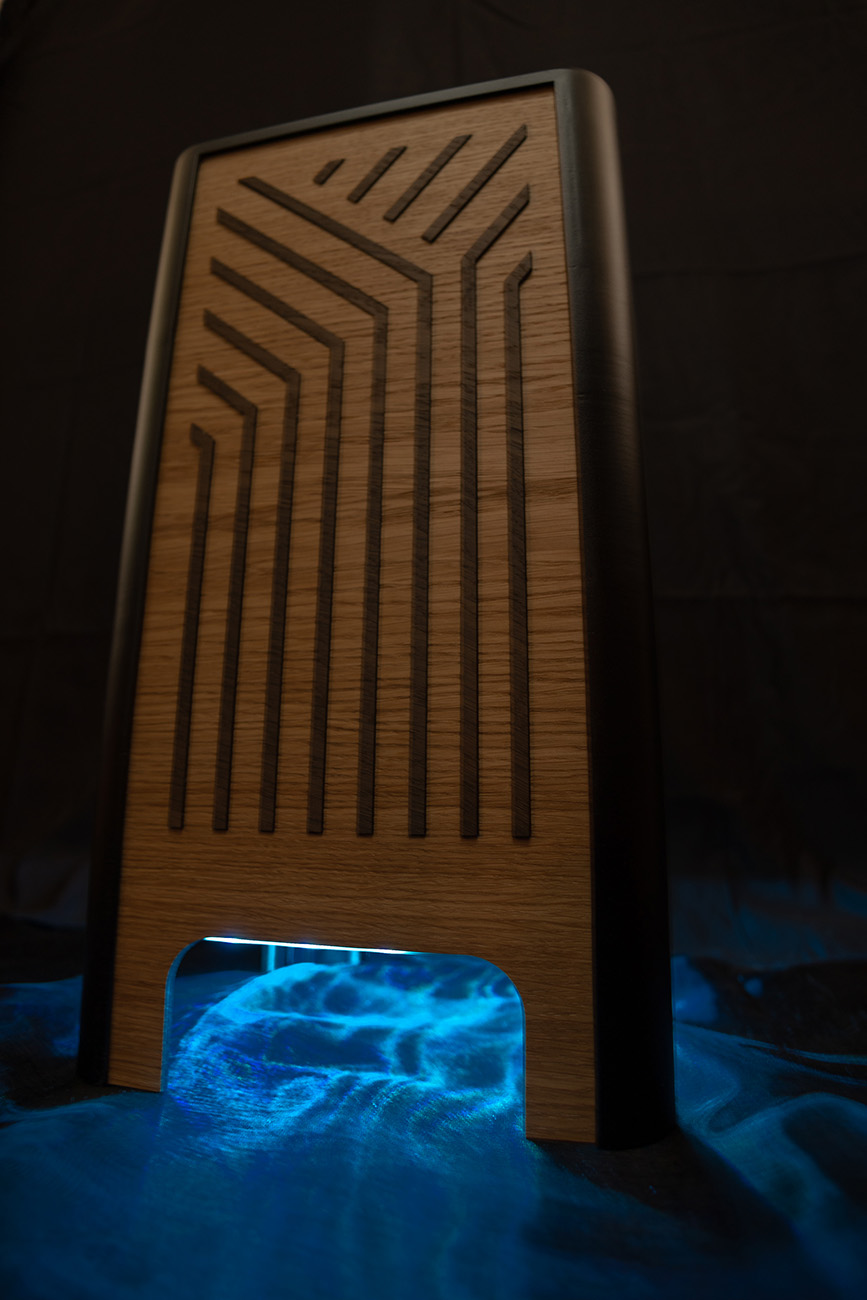
Oh yes, LEDs! I’m usually not a fan of lights blinking in all kinds of colors. But I do like the muted glowing ambiance LEDs can create if done right. Putting them on the bottom of the frame would have the light spill out from the openings in the bottom and light up the floor somewhat in a nice way. I hoped. The LEDs I bought on sale support RGB but aren’t individually adressable; ie, all of the LEDs will have the same color. Which fit well with my idea of having them as ambiance.
I hadn’t designed the inner frame to include space for LEDs so it was a pretty cramped fit, I printed angled brackets that mounted to the frame and then used double-sided adhesive to fix the LEDs to the brackets.
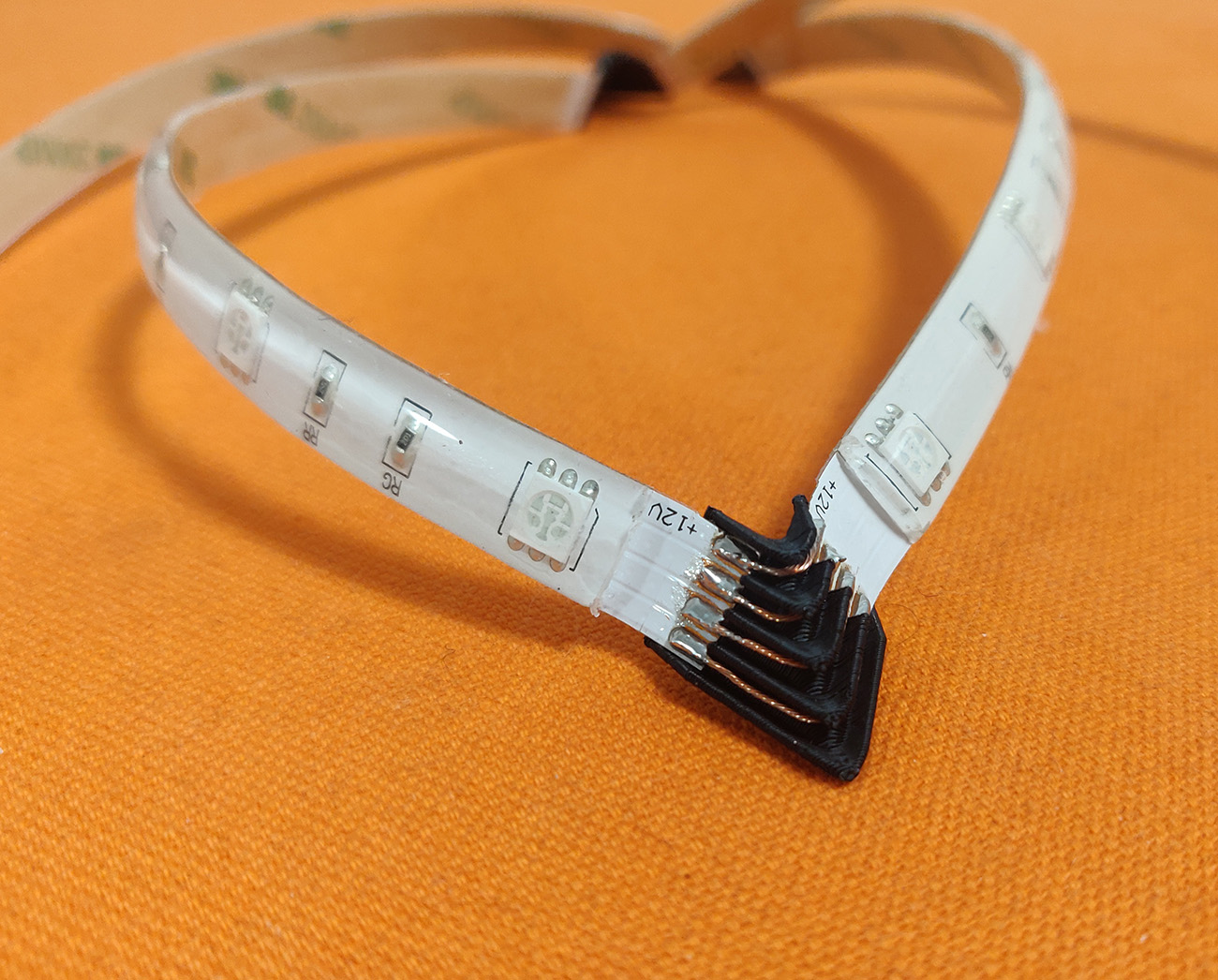
There wasn’t much space available to connect the LED-strips together so I made small corner cable channels with short pieces of cable. It took way too long for my brain to figure out how to design and fit these corner connectors, it’s a bit tricky to create something that rotates along two axes.
Building the outer case
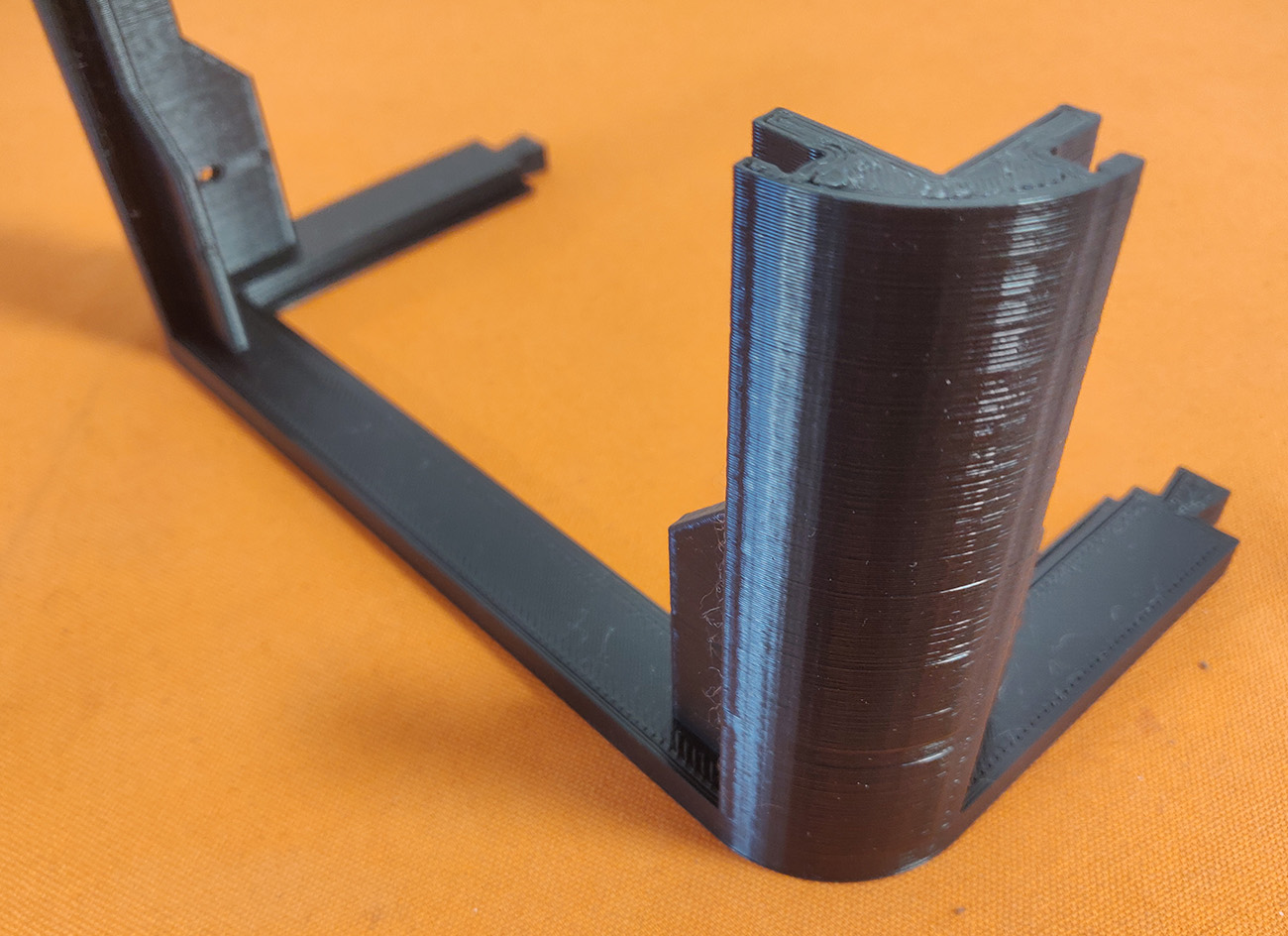
With the internal frame mostly done the next big step was printing the plastic corner pieces for the outer case. These would later hold on to the plywood sides. As the outer case is larger than my printbed I had to print them all in pieces and then glue them together into a single piece.
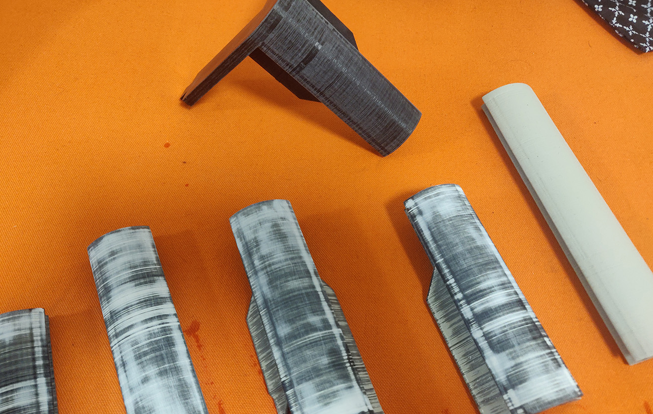
It took almost a kilogram of plastic and a whole lot of sanding & filling to get the surfaces nice & smooth. This was the first time I’d worked with fillers which did wonders with some of the uneven printing I had (I’ve had some issues with my printer recently). Though it took quite a lot of time to repeatedly fill & sand.
After gluing everything together it was a huge relief that the outer case fit nicely onto the inner frame.
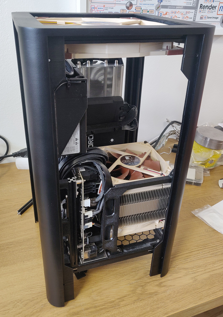
And after a few coats of spray paint it went from looking ugly to pretty nice.
Locking the case
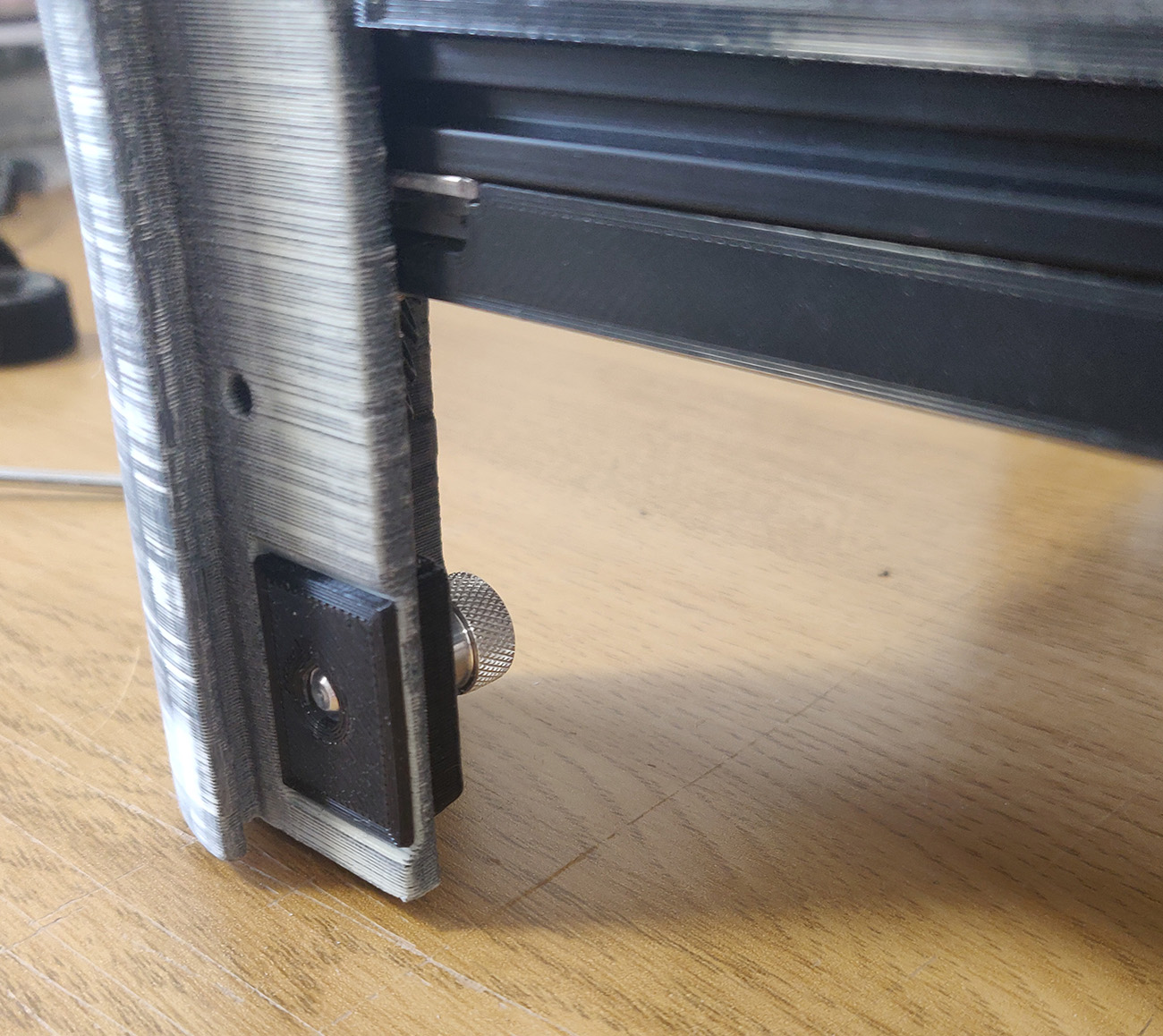
A big issue I had been pondering for a long time was how I would secure the outer case to the inner frame. Sure, it’s great that it’s easy to take the outer case on and off but what happens when you want to carry the whole thing? I had to figure out some way of locking the two pieces together.
Enter thumbscrews, an incredibly simple but solid solution. Sure, it’s not the easiest one but unscrewing four thumbscrews doesn’t take long. But screw threads in plastic are prone to break so I didn’t want to have the threads be part of the full frame. Instead I created a small threaded piece that would clamp the outer case to the inner frame. So if the thread breaks I can just print the small piece again and swap it out.
Plywood sides
With the plastic frame mostly done I switched focus to the plywood sides. As I don’t have a wood workshop anymore I ordered lasercut oak plywood from Cotter.
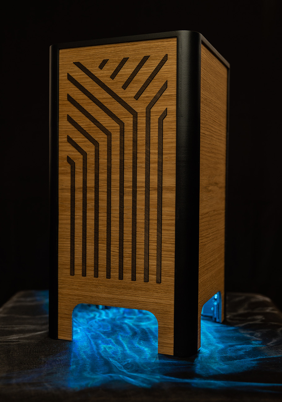
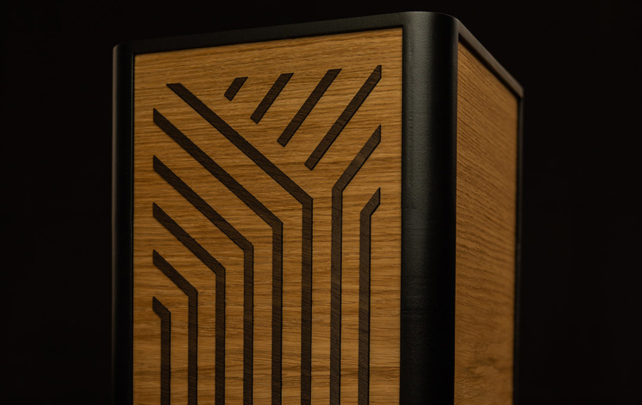
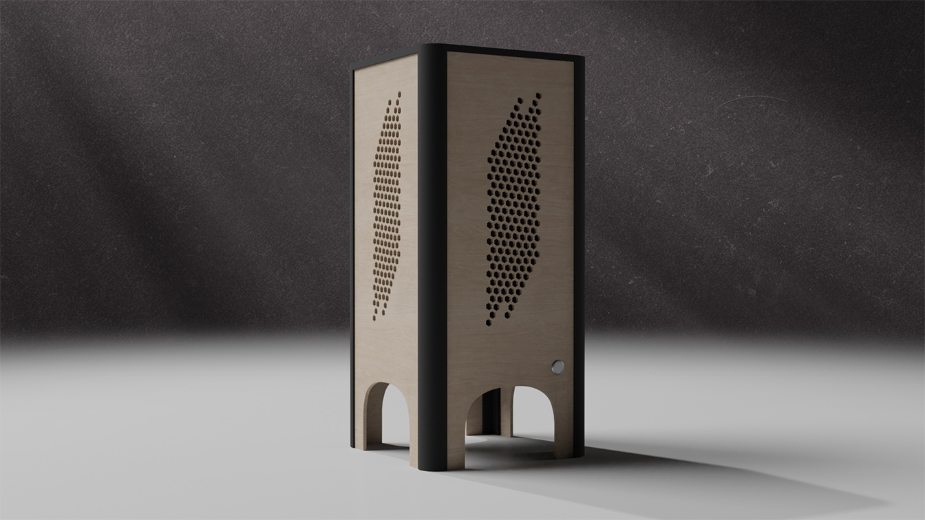
Even though I wanted the design to be clean I also wanted some kind of pattern on the front. I made a simple honey-comb design early on but I never got attached to it. During my build Fractal Design released a case called Torrent and I immediately fell in love with the pattern on the front. I did a quick copy of the design in my 3D model and I loved it, it fit perfectly. So I decided to use it myself, please don’t sue me Fractal Design.
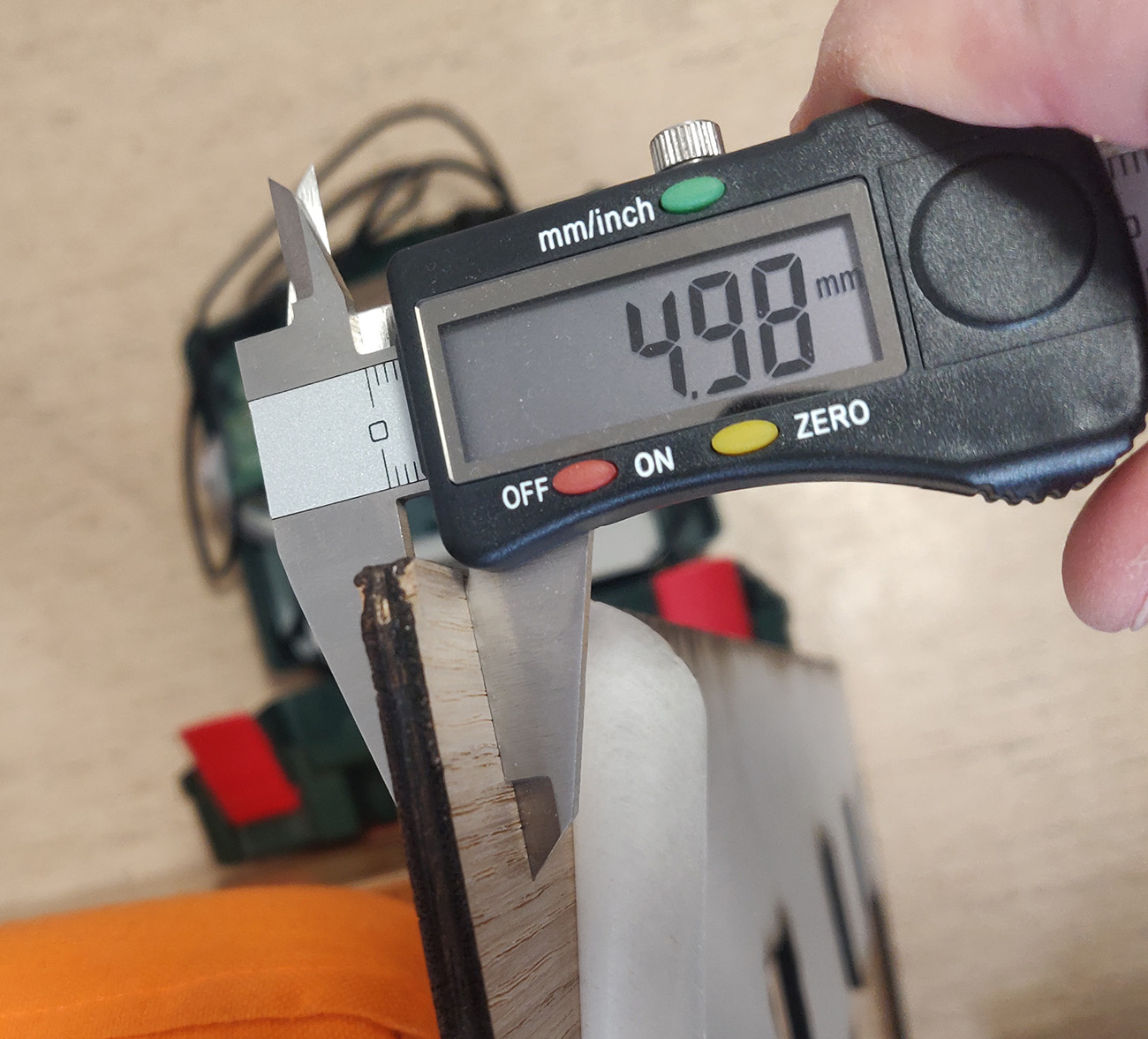
Well, turns out that Cotter’s supplier of oak veneered plywood had changed their material. Instead of being 4mm thick it was 5mm, an error-margin of 25% which was way above the 10% I had calculated into my design. So I had to spend a lot of grueling time sanding down the sides to get them closer to 4mm so that they would fit into the plastic frame. Cotter were pretty nice though, they reimbursed me for the order.
GPU Filter
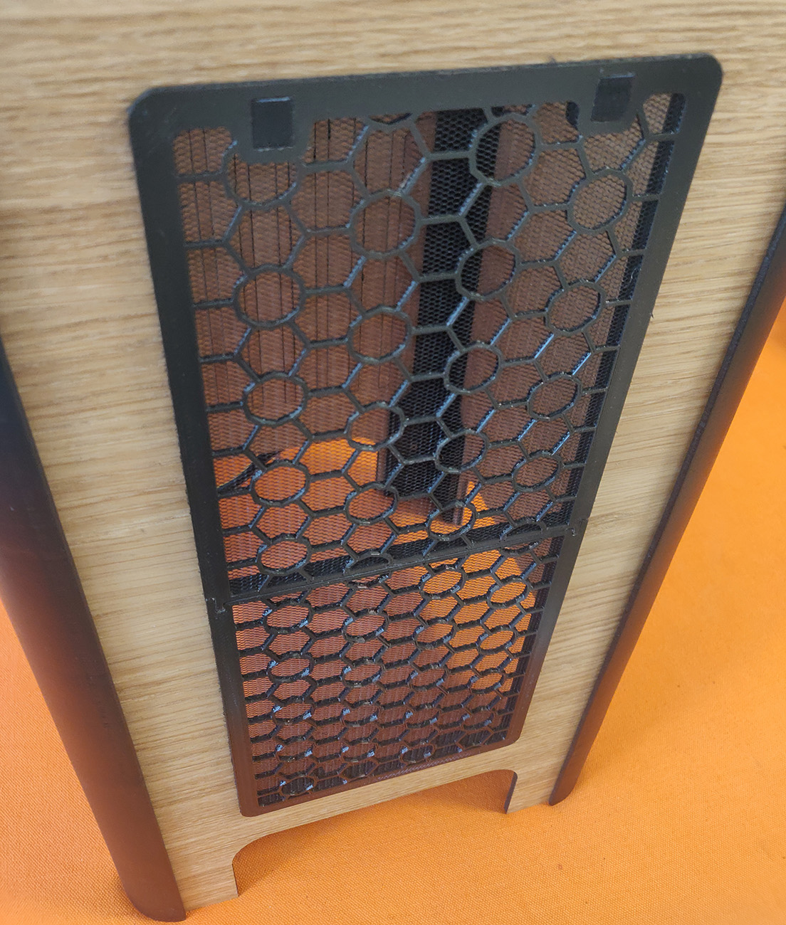
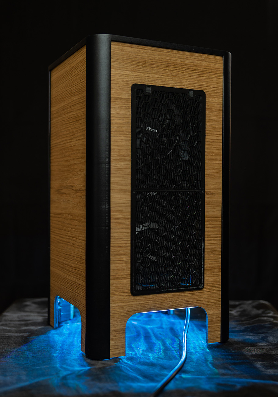
The GPU would also be pulling in air so similarly to the CPU I created a fan filter here too. I switched out the pattern I used for the CPU filter to a nice one I had designed myself on Polygonia. And of course the filter is removable also so that you can clean it. The design was larger than my printbed so once again I had to print it in two parts and then glue them together.
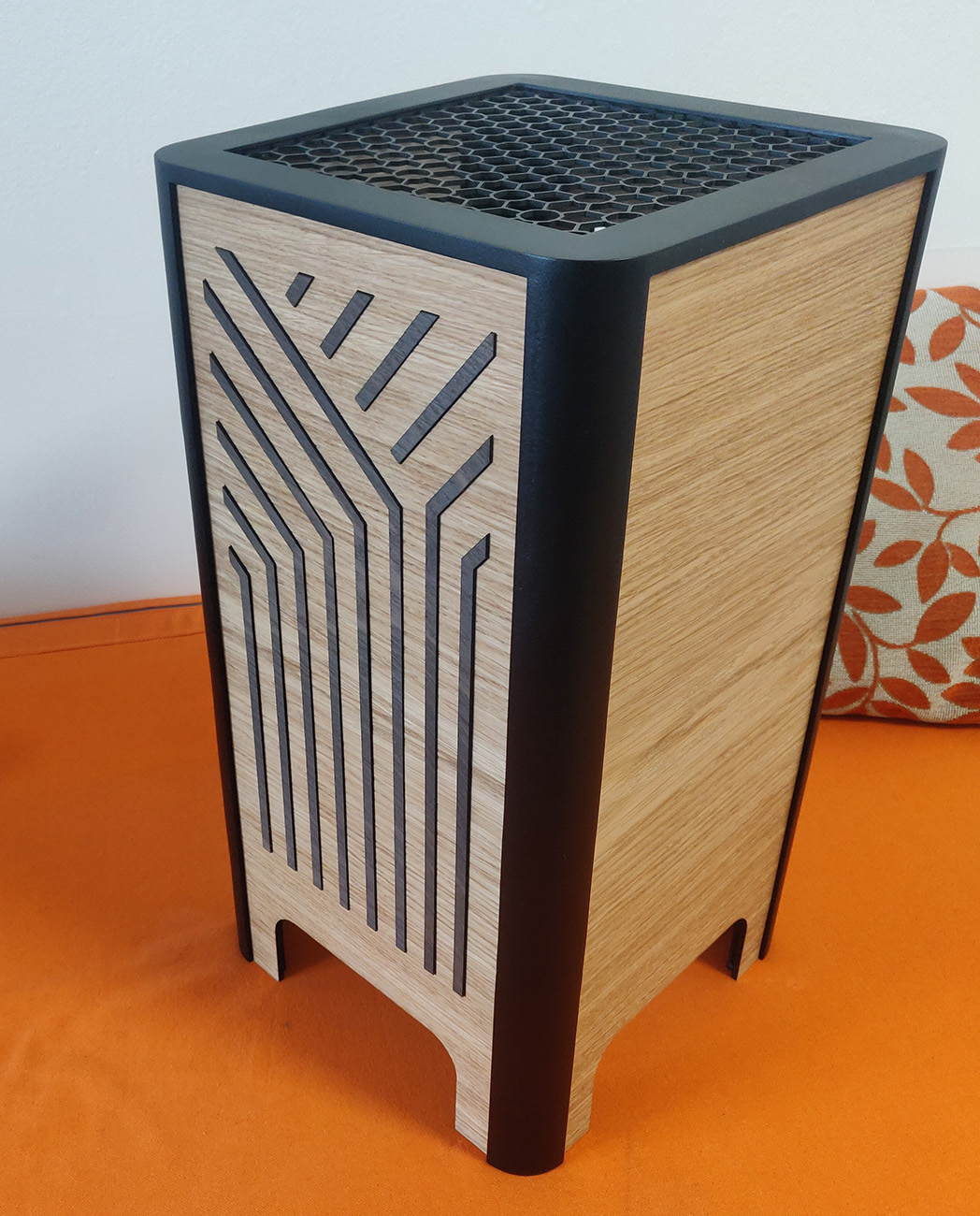
After adding a finish on the wood and gluing in the dark oak pieces in the front the case was complete! Note that I also used the Poligonia pattern for a top fan cover as well, I wanted to ensure that if one of our cats jumped up on the case she wouldn’t get hit by the 200mm exhaust fan.
Completion
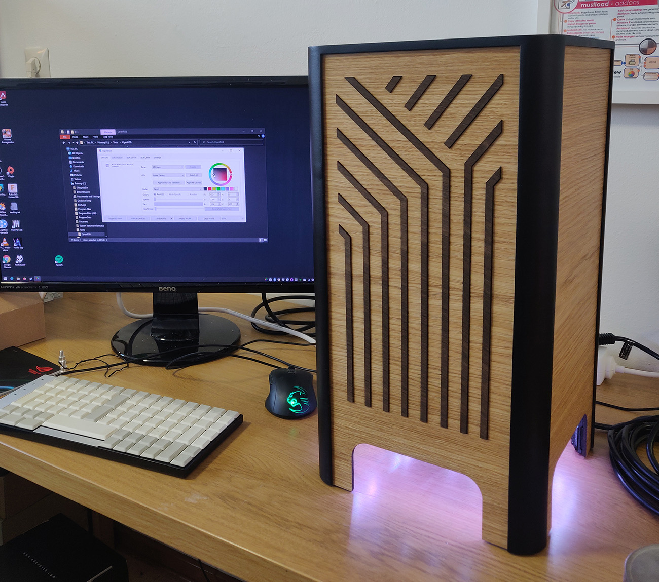
With everything done I could finally boot it up and try it out. After fixing an issue with the LEDs having two colors swapped it was finished! That sure was a good day, I was so incredibly proud and happy. The case really had become everything I hoped for!
Sure, there are some places where the print layers are still visible even after all my work filling & sanding. And the CPU filter doesn’t sit as snugly as I’d hoped. But I’m ok with that, sometimes you just have call it a day and be happy with what you got.
I felt that after having spent so much time building this case I should probably take some professional photos of it, it would be a shame if it wouldn’t get to live up to it’s true glory. Luckily I have a friend who does some photography on the side so he helped me out with a photoshoot which you can see some images from below.
Thank you for taking the time to read all the way through this post, I hope it was interesting and maybe even a bit inspiring! If you have any questions about the build or design then just shoot me a message. Definitely send me a message if you start your own case, I’d love to see it. Take care!
Photoshoot